This is my first time, and I'm looking for guidance on my approach to a particular problem: ensuring that a Solid State Relay (SSR) closes whenever my Arduino Nano loses power. The SSR, powered by the Arduino Nano's 5V pin, is designed to activate a bulb either during specific trigger events (as programmed in the Arduino) or when the AC-DC adapter, powering Arduino Nano, wall socket loses power.
To maintain power to the SSR in the event of an Arduino power failure, I have set up a backup system using 3 AA batteries. The challenge is to create a circuit that switches to battery power only when the Arduino is unable to supply power. My current design utilizes 2 Schottky diodes. However, to prevent current leakage (which is dangerous to non-rechargeable AA batteries), I have used a P-channel MOSFET to block reverse current flow.
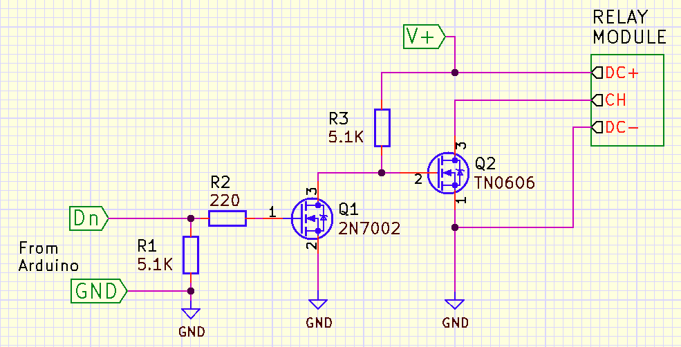
Here is the circuit diagram for reference:
And here is the link to datasheet of OMRON G3MB-202P (1565E) that is used in SSR module that I would be using: G3MB.pdf (digikey.com).
I am seeking assistance with the following:
Confirmation that this circuit effectively prevents backflow current when the Arduino's power supply is active.
Assurance that the battery will not drain while the Arduino's power source is dominant.
Verification that the circuit switches to the battery source within an acceptable delay (less than 0.5 seconds) when the Arduino loses power.
4.Guidance on connecting the SSR (which is low trigger so needs to be grounded to activate) to one of the digital pins on the Arduino Nano, especially considering the common ground shared when the battery source is used.
I apologize for the following:
The circuit diagram is not complete; additional resistors are needed
to prevent short-circuiting. The image is meant to convey the basic
principle rather than a detailed schematic.
The relay channel pin control circuit is not connected, as I am uncertain about this
aspect.
I have used the symbol for a Zener diode instead of a
Schottky diode, and the SSR symbol is not accurate due to limitations
in the diagramming tool I used.
Instead of a traditional schematic, I
have provided an image for ease of creation.
I have posted this query
on multiple platforms to reach a broader audience and gather diverse
insights.
I greatly appreciate any help or advice on this project.
I rechecked the part number. It is the same as what is written on the datasheet. To verify I also checked the Relay on a breadboard and it does turn on when a LOW state is given. I don't know why the datasheet has the same part number but a different SSR or if there is a reverse mechanism (if that is possible) on a module that makes this Low Triggered. Here is the link to module.
So you are using a Module/board and not the bare relay, is that correct?
I'm having problems connecting o the link you gave, seem to be down
Ok works now
That circuit only takes care of making sure that the relay stays on when the arduino has no power.
As I said we still need to figure out a good way to power everything with batteries.
The problem is that the relay need at least 4V to turn on. Partially discharged AA batteries can be around 1.25V. That will be only 3.75V.
I think a 9 volt battery would be better for space requirements. So I need to create a Voltage dropper. I'm very new, can you also help in creating a voltage dropper too? And we need to make sure the Battery doesn't get significantly drane when Arduino is powered
I couldn't find any PCB house that did Assembly too at a reasonable rate and quantity, so I would need to solder them myself. And I've never done SMD. Thus I prefer through hole if possible. Also, I noticed High Trigger SSR came back in stock today, so if it saves money, complexity or PCB space - I can order it.
Through hole is OK
Do you have a link to the high trigger model?
Also if you ate going to hand solder a PCB why don't you use the bare relay rather than the module.
It's fine for me to take the SSR out of board, if I can somehow confirm that the circuit works before attempting to test on a live wire, as SSR can't be tested in a DC load setup (or I think so). I also need to know what precautions I should take when dealing with AC load on PCB, like do I've to change anything on standard PCB design or add any component?
India follows the IS12360 standard that requires low voltage single phase supply to be delivered at 230V, with the minimum and maximum value ranging from 207V to 253V. Frequency is 50Hz.
I need to control a load of max 25 W (range of 10W - 20W)