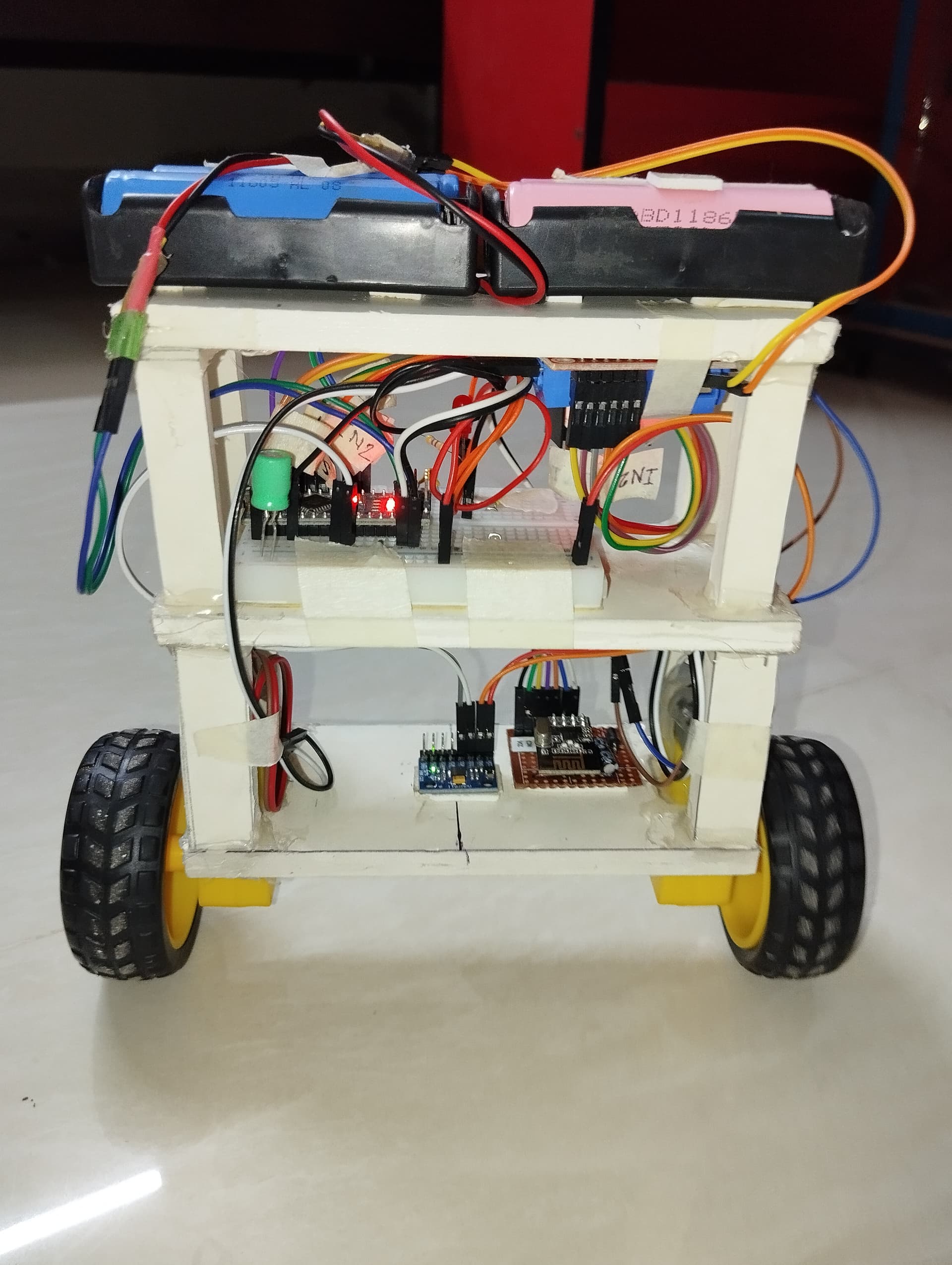
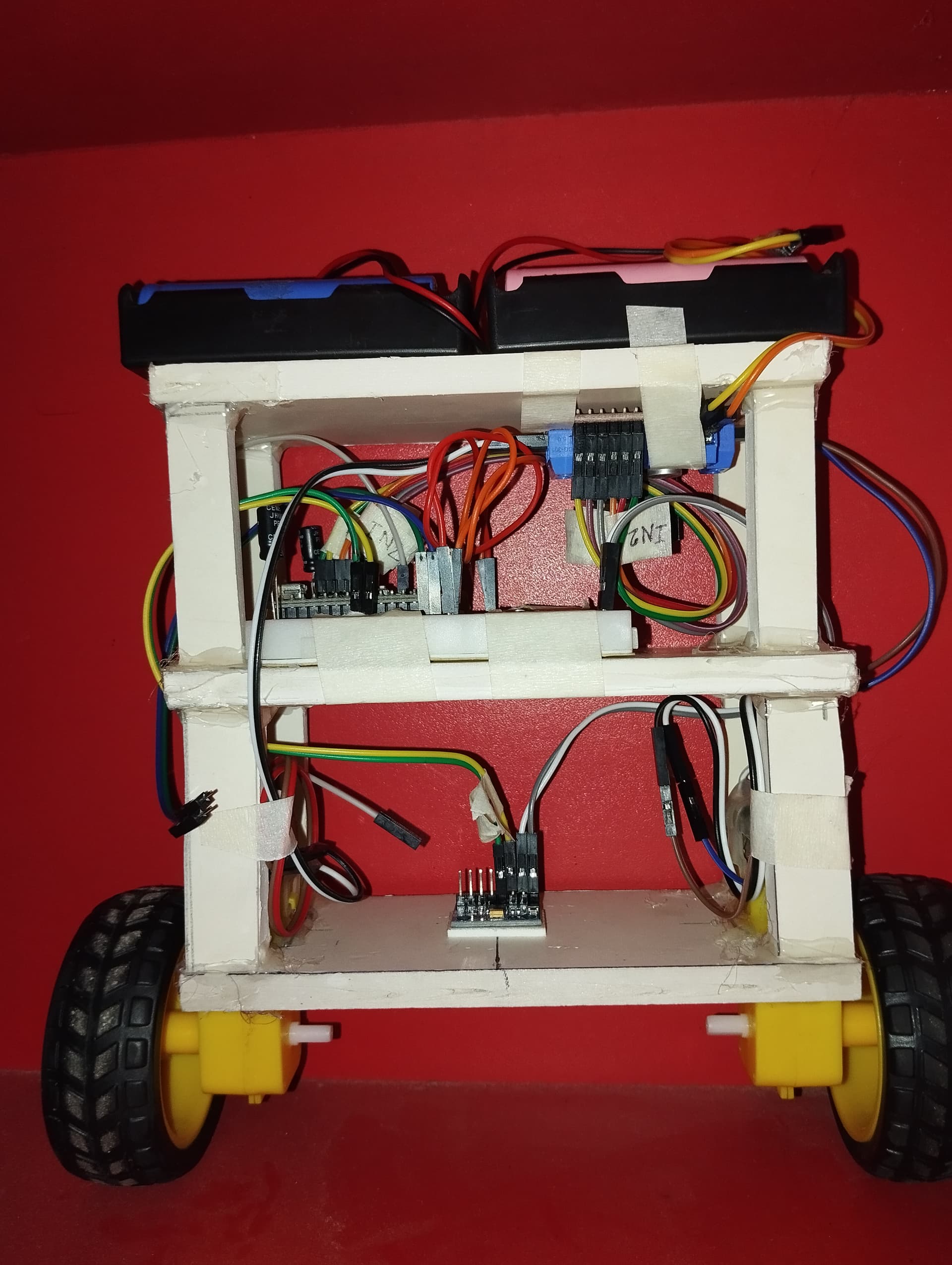
I am using Arduino Nano, MPU6050, l298n motor driver module and 6v dc geared motor to create a 2 wheel self balancing robot.
I am sharing the code below:
// Uncomment to print the MPU data on the serial monitor for debugging
//#define PRINT_DEBUG_BUILD

// PID library
#include <PID_v1.h>

// These are needed for MPU
#include "I2Cdev.h"
#include "MPU6050_6Axis_MotionApps20.h"

#if I2CDEV_IMPLEMENTATION == I2CDEV_ARDUINO_WIRE
    #include "Wire.h"
#endif

// class default I2C address is 0x68
MPU6050 mpu;

#define INTERRUPT_PIN 2  // use pin 2 on Arduino Uno & most boards

// MPU control/status vars
bool dmpReady = false;  // set true if DMP init was successful
uint8_t mpuIntStatus;   // holds actual interrupt status byte from MPU
uint8_t devStatus;      // return status after each device operation (0 = success, !0 = error)
uint16_t packetSize;    // expected DMP packet size (default is 42 bytes)
uint16_t fifoCount;     // count of all bytes currently in FIFO
uint8_t fifoBuffer[64]; // FIFO storage buffer

// orientation/motion vars
Quaternion q;           // [w, x, y, z] quaternion container
VectorFloat gravity;    // [x, y, z] gravity vector
float ypr[3];           // [yaw, pitch, roll] yaw/pitch/roll container and gravity vector
VectorInt16 gy;         // [x, y, z] gyro sensor measurements

// ================================================================
// === INTERRUPT DETECTION ROUTINE ===
// ================================================================

volatile bool mpuInterrupt = false;  // indicates whether MPU interrupt pin has gone high
void dmpDataReady() {
    mpuInterrupt = true;
}

#define PID_MIN_LIMIT -255  // Min limit for PID
#define PID_MAX_LIMIT 255   // Max limit for PID
#define PID_SAMPLE_TIME_IN_MILLI 10  // PID sample time in milliseconds

// The pitch angle given by MPU6050 when the robot is vertical and MPU6050 is horizontal is 0 in the ideal case.
// However, in reality, it's slightly off and we need to add some correction to keep the robot vertical.
// This is the angle correction to keep our robot standing vertically. Sometimes the robot moves in one direction so we need to adjust this.
#define SETPOINT_PITCH_ANGLE_OFFSET .1

#define MIN_ABSOLUTE_SPEED 20  // Min motor speed

double setpointPitchAngle = SETPOINT_PITCH_ANGLE_OFFSET;
double pitchGyroAngle = 0;
double pitchPIDOutput = 0;

double setpointYawRate = 0;
double yawGyroRate = 0;
double yawPIDOutput = 0;

#define PID_PITCH_KP 65
#define PID_PITCH_KI 500
#define PID_PITCH_KD 1.5

#define PID_YAW_KP 0
#define PID_YAW_KI 0
#define PID_YAW_KD 0

PID pitchPID(&pitchGyroAngle, &pitchPIDOutput, &setpointPitchAngle, PID_PITCH_KP, PID_PITCH_KI, PID_PITCH_KD, DIRECT);
PID yawPID(&yawGyroRate, &yawPIDOutput, &setpointYawRate, PID_YAW_KP, PID_YAW_KI, PID_YAW_KD, DIRECT);

int enableMotor1 = 10;
int motor1Pin1 = 7;
int motor1Pin2 = 8;

int motor2Pin1 = 6;
int motor2Pin2 = 5;
int enableMotor2 = 9;

void setupPID() {
    pitchPID.SetOutputLimits(PID_MIN_LIMIT, PID_MAX_LIMIT);
    pitchPID.SetMode(AUTOMATIC);
    pitchPID.SetSampleTime(PID_SAMPLE_TIME_IN_MILLI);

    yawPID.SetOutputLimits(PID_MIN_LIMIT, PID_MAX_LIMIT);
    yawPID.SetMode(AUTOMATIC);
    yawPID.SetSampleTime(PID_SAMPLE_TIME_IN_MILLI);
}

void setupMotors() {
    pinMode(enableMotor1, OUTPUT);
    pinMode(motor1Pin1, OUTPUT);
    pinMode(motor1Pin2, OUTPUT);

    pinMode(enableMotor2, OUTPUT);
    pinMode(motor2Pin1, OUTPUT);
    pinMode(motor2Pin2, OUTPUT);

    rotateMotor(0, 0);
}

void setupMPU() {
    // join I2C bus (I2Cdev library doesn't do this automatically)
    #if I2CDEV_IMPLEMENTATION == I2CDEV_ARDUINO_WIRE
        Wire.begin();
        Wire.setClock(400000); // 400kHz I2C clock. Comment this line if having compilation difficulties
    #elif I2CDEV_IMPLEMENTATION == I2CDEV_BUILTIN_FASTWIRE
        Fastwire::setup(400, true);
    #endif

    mpu.initialize();
    pinMode(INTERRUPT_PIN, INPUT);
    devStatus = mpu.dmpInitialize();

    // supply your own gyro offsets here, scaled for min sensitivity
    mpu.setXAccelOffset(-429);
    mpu.setYAccelOffset(-1701);
    mpu.setZAccelOffset(1161);
    mpu.setXGyroOffset(-5);
    mpu.setYGyroOffset(-6);
    mpu.setZGyroOffset(15);

    // make sure it worked (returns 0 if so)
    if (devStatus == 0) {
        // Calibration Time: generate offsets and calibrate our MPU6050
        // mpu.CalibrateAccel(6);
        // mpu.CalibrateGyro(6);
        // turn on the DMP, now that it's ready
        mpu.setDMPEnabled(true);
        mpuIntStatus = mpu.getIntStatus();
        dmpReady = true;
        // get expected DMP packet size for later comparison
        packetSize = mpu.dmpGetFIFOPacketSize();
    } else {
        // ERROR!
        Serial.print(F("DMP Initialization failed (code "));
        Serial.print(devStatus);
        Serial.println(F(")"));
    }
}

void setup() {
    Serial.begin(9600);
    setupMotors();
    setupMPU();
    setupPID();
}

void loop() {
    // if programming failed, don't try to do anything
    if (!dmpReady) return;

    // read a packet from FIFO. Get the Latest packet
    if (mpu.dmpGetCurrentFIFOPacket(fifoBuffer)) {
        mpu.dmpGetQuaternion(&q, fifoBuffer);
        mpu.dmpGetGravity(&gravity, &q);
        mpu.dmpGetYawPitchRoll(ypr, &q, &gravity);
        mpu.dmpGetGyro(&gy, fifoBuffer);

        yawGyroRate = gy.z;  // rotation rate in degrees per second
        pitchGyroAngle = ypr[1] * 180/M_PI;  // angle in degree

        pitchPID.Compute();
        yawPID.Compute();

        rotateMotor(pitchPIDOutput + yawPIDOutput, pitchPIDOutput - yawPIDOutput);

        #ifdef PRINT_DEBUG_BUILD
            Serial.print("Yaw Rate: ");
            Serial.println(yawGyroRate);
            Serial.print("Yaw PID Output: ");
            Serial.println(yawPIDOutput);
            delay(500);
        #endif
    }
}

void rotateMotor(int speed1, int speed2) {
    if (speed1 < 0) {
        digitalWrite(motor1Pin1, HIGH);
        digitalWrite(motor1Pin2, LOW);
    } else {
        digitalWrite(motor1Pin1, LOW);
        digitalWrite(motor1Pin2, HIGH);
    }

    if (speed2 < 0) {
        digitalWrite(motor2Pin1, HIGH);
        digitalWrite(motor2Pin2, LOW);
    } else {
        digitalWrite(motor2Pin1, LOW);
        digitalWrite(motor2Pin2, HIGH);
    }

    speed1 = abs(speed1) + MIN_ABSOLUTE_SPEED;
    speed2 = abs(speed2) + MIN_ABSOLUTE_SPEED;

    speed1 = constrain(speed1, MIN_ABSOLUTE_SPEED, 255);
    speed2 = constrain(speed2, MIN_ABSOLUTE_SPEED, 255);

    analogWrite(enableMotor1, speed1);
    analogWrite(enableMotor2, speed2);
}
I found this code online as it is just edited the gyro offsets for mpu 6050 and tuned the PID values.
First Problem is the robot balances pretty well without the interrupt pin of mpu6050 is being connected to Arduino via digital pin 2. If I connect the interrupt pin the motors behaves abnormally. Sometimes they run at their full speed regardless of the pitch angle, or sometimes it balance for a few seconds and then motors stop completely.
But the code has defined interrupt pin. I am not sure if the interrupt is necessary and how the robot is working fine without this although it is mentioned in the code.
Second Problem is the robot occasionally tends to rotate left or right. I tried to put some values in 'Yaw PID'. But I am unable to figure out any patterns. If I put 1 to kP it becomes too much aggressive. I tried putting 0.01 it is same as putting 0. I am not sure how can I stop this abnormal rotation.
I have uploaded two short video on google drive. I am sharing the links below. I think this may provide better understanding of the situation.
**I am using two separate battery set each consisting 2x 18650 lithium batteries. One for powering Arduino and another for powering motor driver. **
I am uploading the arduino code also.
Balanced_Robot_4.ino (6.5 KB)