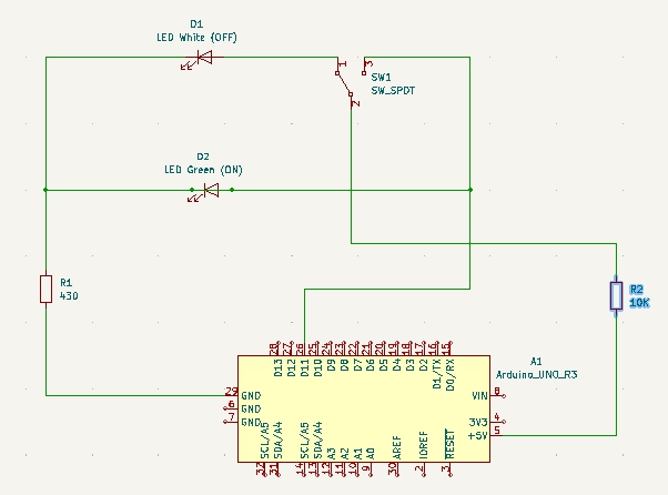
I have an already designed enclosure for a DPDT switch with 2 LEDs (white=OFF, green=ON).
- The common lead is fed by +5V from Arduino Mega board.
- The OFF lead goes to the WHITE LED, then forks into the LED-protect resistor.
- The ON lead goes to the GREEN LED, then forks into the LED-protect resistor.
- The LED-protect resistor goes to Arduino GND.
- The ON lead also goes to Arduino D11 INPUT pin (bypassing GREEN LED).
Arduino D11 is meant to register the position of the switch.
In this configuration, the D11 never changes (it always reads OFF, regardless of switch position).
I added a 10K resistor between the switch ON lead and D11, so now D11 reads OFF when the switch is off. However, it now alternates between ON and OFF when the switch is ON.
Also, it takes 3 seconds for D11 to read OFF when the switch is turned to the OFF position.
Is there an easy way to make this circuit work as desired (so D11 reads ON/OFF correctly), or is it doomed (i.e., my self-contained, already-made, back of the console component must be redesigned)?
CODE:
const int MOTOR_SWITCH_PIN = 11;
const int MOTOR_ENABLE_PIN = 10;
**(ellipsis)**
void setup() {
  Serial.begin(9600);

  pinMode(MOTOR_SWITCH_PIN, INPUT);
  pinMode(MOTOR_ENABLE_PIN, OUTPUT);
**(ellipsis)**
}

void loop() {
  if (motorSwitchIsOn())
    Serial.println("MOTORS ON");
  else
    Serial.println("MOTORS OFF");
**(ellipsis)**
}

bool motorSwitchIsOn () {
  int value = digitalRead( MOTOR_SWITCH_PIN );
  Serial.print(value);
  Serial.print(":");
  return !value;
}
**(ellipsis)**
