I have a instrument which keeps sending CAN messages as below :
This uses the extended ID. I want to be able to receive this using the MCP2515 module + Arduino UNO.
Is it possible if I use the MCP2515 library or I need to use some other library ?

I have a instrument which keeps sending CAN messages as below :
This uses the extended ID. I want to be able to receive this using the MCP2515 module + Arduino UNO.
Is it possible if I use the MCP2515 library or I need to use some other library ?
It might work. If the time stamps on the left of the image are milliseconds then you have 3 milliseconds between messages which is probably OK for an Arduino MC2515 combination.
mikb55:
It might work. If the time stamps on the left of the image are milliseconds then you have 3 milliseconds between messages which is probably OK for an Arduino MC2515 combination.
My main concern is on the extended ID. Is the MCP2515 library capable of handling that ?
Sorry to ask this as right now I don't have the hardware on hand to check and yet to fully go through the library.
Timing is not critical and I am happy with a 100 ms intervale between reads.
Thanks !
There are many libraries to choose from. Some good, some not so good. They all work to some degree.
The only one I've used in a real project is the GitHub - coryjfowler/MCP_CAN_lib: MCP_CAN Library library which does have support for extended IDs.
If you are doing infrequent reads then bear in mind that the MCP2515 is always receiving data and has a 2 message receive buffer that once full stays that way until you read it. Doing a read always pulls data from the buffer, so if you want up to date data you need to read and discard the first two messages and then wait for a new one to arrive.
mikb55:
There are many libraries to choose from. Some good, some not so good. They all work to some degree.The only one I've used in a real project is the GitHub - coryjfowler/MCP_CAN_lib: MCP_CAN Library library which does have support for extended IDs.
Great .. this library looks exactly the one i wanted as it explicitly handles extended ID. Let me check and revert. I guess this should work for my use as its a simple requirement to receive and send some messages once every 100ms or so.
Thanks
OK now the Receive example code in the MCP_CAN_Lib worked the first shot.
I then tried the Send Example code. I modified the PGN+SA to 0xFF0122 to suit the Receiver and sent a 8 byte array. I have a basic doubt on forming the 8 byte array... my CAN receiver expects a value of 8 bits ( decimal 0-255). So how do I format the data ? I am now sending 8 bytes with the LSB set to 125 which is what I want to try.
After the initialization I get a "Error Sending Message " report. And the Receiver reports a time out error. So what is the mistake in the code below :
#include <mcp_can.h>
#include <SPI.h>

MCP_CAN CAN0(10);     // Set CS to pin 10

void setup()
{
  Serial.begin(9600);

  // Initialize MCP2515 running at 16MHz with a baudrate of 250kb/s and the masks and filters disabled.
  if (CAN0.begin(MCP_ANY, CAN_250KBPS, MCP_16MHZ) == CAN_OK) Serial.println("MCP2515 Initialized Successfully!");
  else Serial.println("Error Initializing MCP2515...");

  CAN0.setMode(MCP_NORMAL);   // Change to normal mode to allow messages to be transmitted
}

byte data[8] = {0x00, 0x00, 0x00, 0x00, 0x00, 0x00, 0x00, 0x7D};  // Send a value of 125

void loop()
{
  // send data:  ID = 0x100, Standard CAN Frame, Data length = 8 bytes, 'data' = array of data bytes to send
  byte sndStat = CAN0.sendMsgBuf(0xFF0122, 0, 8, data);
  if (sndStat == CAN_OK) {
    Serial.println("Message Sent Successfully!");
  } else {
    Serial.println("Error Sending Message...");
  }
  delay(1000);   // send data per 1000ms
}
It looks like the MCP2515 is a CAN- do.
Spec sheet:
I do not separate CAN receive and CAN send routines, If there is something in the receive buffer it needs to be read out before a send, is my understanding. Even though I call this CAN task send, I do both a receive and send in one tasking:
void fSendCAN_Buss( void *pvParameters )
{
  stuSERVO_Message pxServo_Message;
  for ( ;; )
  {
    xEventGroupWaitBits (eg, evtSendCAN_Buss, pdTRUE, pdTRUE, portMAX_DELAY);
    if ( xSemaphoreTake( sema__Send_CAN_Bus, xTicksToWait0 ) == pdTRUE ) // grab semaphore no wait
    {
      CAN_frame_t rx_frame;
      if ( (CAN_cfg.rx_queue != NULL) && (uxQueueMessagesWaiting(CAN_cfg.rx_queue)) ) // if queue not null and something is waiting in queue
      {
        if (xQueueReceive( CAN_cfg.rx_queue, &rx_frame , xTicksToWait0) == pdTRUE )
        {
          if ( rx_frame.MsgID == 2 )
          {
            if ( rx_frame.data.u8[0] == '6' )
            {
               EOT = false;
            }
            if ( rx_frame.data.u8[0] == '4' )
            {
              EOT = false;
              xSemaphoreGive ( sema_HexaPodAdjustment ); // begin walking forward task
            }
          } // if ( rx_frame.MsgID == 2 )
        } // if (xQueueReceive( CAN_cfg.rx_queue, &rx_frame , xTicksToWait5) == pdTRUE )
      } // if ( (CAN_cfg.rx_queue != NULL) && (uxQueueMessagesWaiting(CAN_cfg.rx_queue)) )
      //      // ack the initialization
      if ( xQueueReceive ( xQ_SERVO_Message, &pxServo_Message, QueueReceiveDelayTime ) == pdTRUE )
      {
        rx_frame.FIR.B.FF = CAN_frame_std;
        rx_frame.MsgID = pxServo_Message.MsgID;
        rx_frame.FIR.B.DLC = pxServo_Message.DLC;
        rx_frame.data.u8[0] = pxServo_Message.Instruction;
        rx_frame.data.u8[1] = pxServo_Message.p1;
        rx_frame.data.u8[2] = pxServo_Message.p2;
        rx_frame.data.u8[3] = pxServo_Message.p3;
        rx_frame.data.u8[4] = pxServo_Message.p4; // end of torque to position
        rx_frame.data.u8[5] = pxServo_Message.p5;
        rx_frame.data.u8[6] = pxServo_Message.p6;
        rx_frame.data.u8[7] = pxServo_Message.p7;
        ESP32Can.CANWriteFrame(&rx_frame);
      }
      xSemaphoreGive ( sema__Send_CAN_Bus );
    }  // if ( xSemaphoreTake( sema__Send_CAN_Bus, xTicksToWait0 ) == pdTRUE ) // grab semaphore no wait
  } // the for loop
  vTaskDelete( NULL );
} // void fSendCAN_Buss( void *pvParameters )
The event evtSendCAN_Buss is triggered once a milliSecond.
With CAN0.sendMsgBuf and extended addresses you need to change the second parameter from 0 to 1.
mikb55:
With CAN0.sendMsgBuf and extended addresses you need to change the second parameter from 0 to 1.
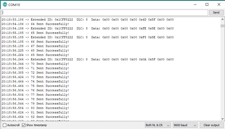
Thanks that did the trick and now I can send / receive. But there is a new problem .. if you look at the code its been designed to send one Tx frame every second and the connected instrument is set to send one frame every second. So its one Tx and one Rx per second. All fine upto 65 seconds. Then the Tx frames start going out rather fast ... almost every 50ms or so. Unable to understand this .. if you look at the attached serial dump you can see my problem. Any idea why this is happening ?
/*
  07 Nov 2019

  Checked OK with the MCP2515 Module.
   Used  NANO board.
   CS to PIN10
   INT to PIN02
   SI to PIN11
   SO to PIN12
   CSK to PIN13
   VCC to 5V
   GND to GND

   Eventhough the XMD default baudrate is 250K this program is at 500K and only then works.

*/

#include <mcp_can.h>
#include <SPI.h>

#define CAN0_INT 2                          // Set INT to pin 2
MCP_CAN CAN0(10);                           // Set CS to pin 10

unsigned int dataToSend ;
byte data[2] = {0x0, 0x0} ;                 //  Sending 32000; Get the required decimal value between 0 and 65000 ; Convert to Hex ; Swap
long unsigned int rxId;
unsigned char len = 0;
unsigned char rxBuf[8];
char msgString[128];                        // Array to store serial string

unsigned int scanLoopInterval  = 1000;
unsigned int scanLoopMs = millis();

//&&&&&&&&&&&&&&&&&&&&&&&&&&&&&&&&&&&&&&

void setup()
{
  Serial.begin(9600);

  // Initialize MCP2515 running at 16MHz with a baudrate of 500kb/s and the masks and filters disabled.

  if (CAN0.begin(MCP_ANY, CAN_500KBPS, MCP_16MHZ) == CAN_OK) {
    Serial.println("MCP2515 Initialized Successfully!");
  }
  else {
    Serial.println("Error Initializing MCP2515...");
  }

  // Change to normal mode to allow messages to be transmitted

  CAN0.setMode(MCP_NORMAL);

  pinMode(CAN0_INT, INPUT);                            // Configuring pin for /INT input
}

//&&&&&&&&&&&&&&&&&&&&&&&&&&&&&&&&&&&&&&

void loop()
{
  readCAN_Msg();                                      // Check incoming datal based on interrupt status

  if ((millis() - scanLoopMs) > scanLoopInterval) {   // Send data
    scanLoopMs = millis();
    dataToSend++;
    if (dataToSend > 65000 ) dataToSend = 0;
    data[0] = lowByte(dataToSend);
    data[1] = highByte(dataToSend);
    sendCAN_Msg();
  }
}

//0000000000000000000000000000000000000000

void sendCAN_Msg() {

  // sendMsgBuf(ExtendedID,1,Data length, data)

  byte sndStat = CAN0.sendMsgBuf(0x1CFF0122, 1, 2, data);
  if (sndStat == CAN_OK) {
    Serial.print(dataToSend);
    Serial.println(" Sent Successfully!");
  }
  else {
    Serial.println("Error Sending Message...");
  }
}

//0000000000000000000000000000000000000000

void readCAN_Msg() {

  if (!digitalRead(CAN0_INT))                        // If CAN0_INT pin is low, read receive buffer
  {
    CAN0.readMsgBuf(&rxId, &len, rxBuf);             // Read data: len = data length, buf = data byte(s)

    if ((rxId & 0x80000000) == 0x80000000)           // Determine if ID is standard (11 bits) or extended (29 bits)
      sprintf(msgString, "Extended ID: 0x%.8lX  DLC: %1d  Data:", (rxId & 0x1FFFFFFF), len);
    else
      sprintf(msgString, "Standard ID: 0x%.3lX       DLC: %1d  Data:", rxId, len);

    Serial.print(msgString);

    if ((rxId & 0x40000000) == 0x40000000) {          // Determine if message is a remote request frame.
      sprintf(msgString, " REMOTE REQUEST FRAME");
      Serial.print(msgString);
    }
    else {
      for (byte i = 0; i < len; i++) {
        sprintf(msgString, " 0x%.2X", rxBuf[i]);
        Serial.print(msgString);
      }
    }
    Serial.println();
  }
}

//****************************************
//               END FILE
//****************************************
It says
"Please note that the return value for millis() is of type unsigned long, logic errors may occur if a programmer tries to do arithmetic with smaller data types such as int. Even signed long may encounter errors as its maximum value is half that of its unsigned counterpart."
mikb55:
millis() - Arduino ReferenceIt says
"Please note that the return value for millis() is of type unsigned long, logic errors may occur if a programmer tries to do arithmetic with smaller data types such as int. Even signed long may encounter errors as its maximum value is half that of its unsigned counterpart."
My bad. Many times when you debug, the obvious is missed as you take it for granted ![]() .
.
Thanks.