I'm looking for advice how to sense human touch on a piece of wood.
Specifically, I'd like to have a circular slice of wood, about 10" in diameter, without visible sensors or electronics, that is triggered when touched with a hand, as reliably as possible.
I have been thinking about a piece of metal foil behind this slice of wood (which could be as thin or thick as needed), with the foil acting as a capacitative sensing material and connecting it to an Arduino with a capacitive sensor sketch.
I would experiment with this approach, but as I'm not really experienced enough it would be a lot more productive if someone could give me some advice how to make this as reliable as possible, or even point me in another direction, to a different method?
I think that you have stated the best approach, already. Experimenting is a (fun) part of the hobby. So try your idea and let us know the results. Start by setting up a conductive touch pad using the Capacitive Sensing Library circuit and example code. Get it to work without the wood, then add the wood over the top and see how it works.
One way is to get the microchip QT101x series chip test board through adafruit. This chip handles most of the nasty stuff of dealing with capacitive touch sensing.
Its totally doable through wood, you'll want to tune the sense capacitance so the touch triggers as your finger smooshes and spreads across the wood. The data sheet is extremely descriptive. The bigger your foil area the harder its going to be to tune.
You'll also want a ground return loop, you can just use a wire that is on the perimeter of the foil.
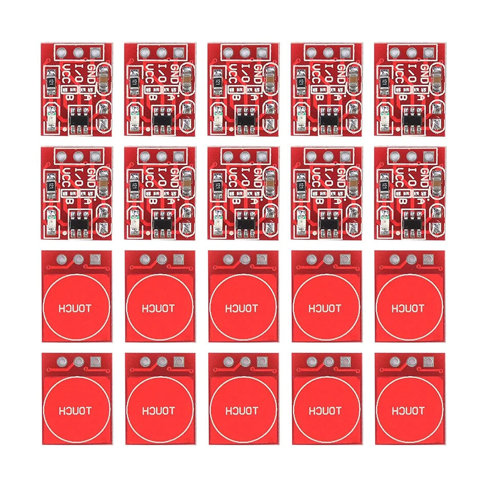
I ended up ordering the TTP223's, now I'm trying to find out if I can connect them all to a single Analog pin, so if one (or more) of the sensors is triggered, that would trigger an LED strip.
Seems like it should be an easy answer to find, but all I find are guides about how to read multiple buttons individually on a single analog pin.
If anyone cares to help some more, I'd really appreciate it.
The datasheet cites "Open drain mode by bonding option, OPDO pin is open drain output". You will have to find out whether they have an open drain output (which I suspect it is), or a push-pull output.
Set one up on a breadboard. Connect the output pin first through a 1k resistor to the cathode of a LED with its anode to the supply voltage. See how the LED responds to touch.
Then connect the output pin through the 1k resistor to the anode of a LED with its cathode to ground. Again, see how the LED responds to touch. If the LED does not work with this connection, then it is "open-drain" and you can directly connect a number of them to the one input and it will signal when any one of them is touched - but you will of course not know which was touched.
Not sure why you would want more than one sensor however, since you would generally simply be connecting the touch terminal on the module to the foil on the back of the wood. Perhaps you should elaborate what you are actually doing now?
I remember they're push/pull, no need for external pull-up. So you can use them with an analog input and resistor ladder to see which one is activated.
This is the latest version of what I'm thinking - this would like a solid single piece of wood, which would be the best in terms of visual appearance :
The sensors are positioned behind the surface so that placing a hand anywhere on the block of wood should trigger at least one of them.
And when any one gets triggered, the same action should happen. (An LED strip lights up (actually quite a lot of them, but I've got that part already working.))
By default they're active high. Place a diode in each sensor's output, cathode pointing to the Arduino, and add a pull-down resistor (10k will do). That's a basic OR port: if any one sensor goes high, the pin pulled high, while the other sensors are unaffected.
There are several project tutorials and schematics on Google that use the output to drive an LED, with LED between output adn GND. That means it must be a push/pull output.
While I have you here and willing to help - is there a specification for the diodes I need? I've never worked with them before, so forgive me if the question sounds silly.
I got all the materials and got everything connected together, but it seems to work only if I don't connect the resistor to ground.
But it works! Is there a problem if there is no resistor connected?
There is also another slight issue - when I have the signal wires connected via a diode for each sensor, I sometimes get residual signals coming into the arduino.
What I mean by that, is that the LED on the TTP223 is turning on/off correctly, but the arduino's LED and the serial monitor are sometimes still triggered for a few seconds after I put my finger of the sensor.
It's like the diode would continue to provide a little bit of current of its own, (like a small capacitor?) after the sensor stops sending out a signal.
Does this sound logical? Is there a way to remedy this?
Just checked the datasheet, at the bottom of p.2 it's confirmed the output is push/pull. So that's not the problem.
What resistor value are you using for the pull-down? It should not be too strong, or the TTP223 may be overloaded and unable to pull high the pin. Around 10k is a good value.
This prevents the pin from floating, which happens when all TTP223 outputs are low. Residual charge (due to a.o. stray capacitance of the wires, the input pin and the diodes) may keep the pin at high level for a while. The 10k resistor makes sure that charge is gone quickly.
 Aliexpress


