I have a ventilation controller board which has a pushbutton to control the speed, at each press the ventilation increases one level and when reaches 3 it starts from 1 again).
The tension at the two poles of the push button is 5V, I think when the button is press the 5V is put on GND. (how can I verify this assumption?)
I'm planning to extend the push button contacts and connect them to a relay controlled by an arduino, and this should be fine.
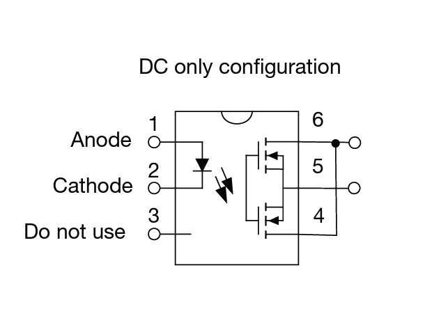
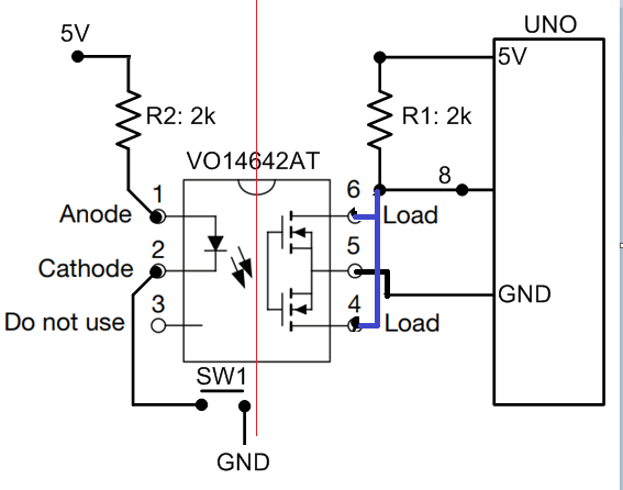
I would like also to have my arduino to be able to identify when the button is pressed manually. One of the ideas I came out with is to use an o the idea would be a spare SSR (VO14642AT), connected to the push button as follows:
Normal operations push button not pressed, SSR is on, the arduino pin is HIGH
Pushbutton is pressed, SSR is off, the arduino pin is LOW
Would this work or there a better logical way to do it? Also the fact that the digital pin would be the majority of time high, and the SSR on is that a potential issue long term?
@GolamMostafa I really appreciate your reply.
Just to clarify, SW1 and the relative 5V and GND are part of a separate PCB independent from the one where I want to run the Arduino and the SSR. So the red line is the separation between the two circuits, is that still correct please?
@TomGeorge yes you are right, in the first schema this was correct, thanks for noticing it.
After the review and a test, I realized that the original pcb with the push button, needs to be modified, and i cannot just extend the two contacts of the push button to the second pcb with the arduino, this is not enough.
i would like to keep the two circuit isolated as they are different. I was thinking as alternative measuring voltage between the two pins of the push button, but want this usually is done with a voltage divider, not sure if i want to keep the two boards independent.
Any suggestion please?
Coming back on this topic and after having given some thoughts.
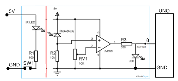
The ventilation controller board has actually a LED which turn on when the system is on the speed 3 which I want to monitor.
My overall goal is to know when the ventilation is on speed 3 which is when the led of the board is on.
I was thinking of placing the SSR in parallel to the LED, as follow and monitor the pin input of the Arduino when low = led on = speed 3 is active.
What do you think of the below please? I still want to keep the two boards totally separated and I cannot modify the original ventilation board if not soldering some jumper cables.
Are you trying to have the Arduino read the button presses? (which doesn't make much sense as the button is still connected to and presumably controlling the device)
Or: are you trying to have the Arduino "press the button" from a distance? (which would make more sense to me)
The post got a bit confused overtime. I explain here again:
I want to remote control the ventilation system I have. This is controlled by a board which has 3 led and a push button. Each led indicates the speed of the ventilation, and with the push button at each press it is possible to cycle through the speeds (1 -> 2 -> 3 -> 1 -> ...) (there is no 0).
The board is part of the ventilation system and cannot be changed. I can though solder some cables to do some connections. I also would like to keep the ventilation board and my arduino board for the remote control separated.
I can already remote control the push button with a relay, now the next step is to understand the speed (1, 2, 3). The next idea I came up with would be to monitor if the led 3 is on. I'm excluding using a LDR.
So I was thinking of using the SSR in parallel with led 3 of the board, so that ideally when the led 3 is on, the SSR is active, and trigger a status change of a digital pin of the arduino.