Hello,
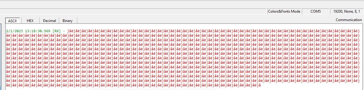
I am trying to debug an issue I have with a project. the project I have is connecting to a weather station through UART. I have narrowed the bug down to the code below. I am using an ATMEGA2560 clone. I am using windows. I have the Arduino clone connected to a DB9 ground to ground (pin 5), RX (pin 2) from DB9 is connected to TX3(pin 14) of Arduino, TX (pin 3) from DB9 is connected to RX3(pin 15) of Arduino. I have included pictures of my connections. The issue I notice is that when I send a command through Serial3 the command gets changed into something else. I do not understand what is going on. I have the Arduino on COM9 and the DB9 connected to COM5. I am using Docklight to simulate the weather station. Has anyone come across an issue like this? Thank you for your time.
void setup() {
// put your setup code here, to run once:
Serial.begin(19200);
Serial3.begin(19200);
}
void loop() {
// put your main code here, to run repeatedly:
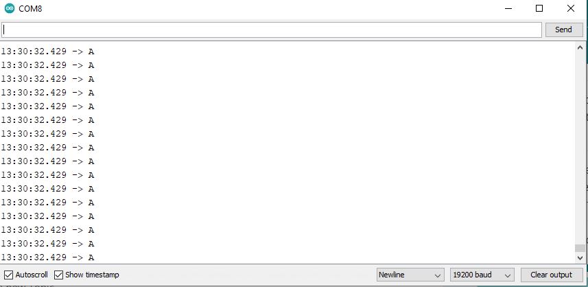
Serial.println("A");
Serial3.println("A");
}
I noticed that If I put Arduino and Docklight in the same COM. The output is correct on docklight. There isn't a problem with the output. Still can't figure out why when I use Serial3 or Serial2 and change the port I get garbage output?
void setup() {
  // put your setup code here, to run once:
  Serial.begin(19200);
//  Serial2.begin(19200);
}

void loop() {
  // put your main code here, to run repeatedly:
  Serial.print("E");
//  Serial2.print("E");

}
I used a DB9 breakout board and used pins of the breakout board 2(RX) ,3(TX),5(GND) to connect to the Arduino. They were connected to 14, 15, gnd respectively. I connected the DB9 breakout board to the USB to RS232 Adapter to connect to the computer. I included links to the tools.
it looks like you have a USB-RS232 cable connected to a RS232 breakout module which gives terminal access to the RS232 signals which typically are voltage levels -12 to +12 volts
in post 1 you then appear to connect the RS232 signals directly to the serial ports of the mega which should be 0V to +5Volts
I think you require an RS232 shield to convert the RS232 signals to TTL levels for the Mega
if you have connected RS232 directly to the Mega it is possible that the Mega is damaged
if you have a multimeter check the voltage levels comming out of the RS232 breakout module