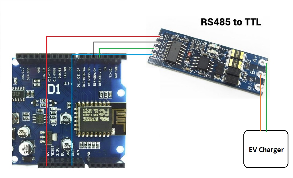
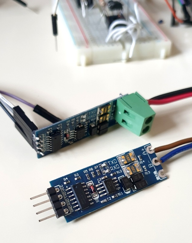
My EV charger comes with the RS485 lines, for connecting to a MODBUS energy meter. Using YAT (Yet Another Terminal) and a USB-TTL-485 interface, I could capture the initial MODBUS request as following:
01h 03h FCh 02h 00h 01h 15h 9Ah
repeating 10 times (timeout)
Simply, the EV charger asks for the model number of the energy meter.
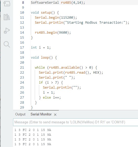
Then, I was trying to write a serial monitor using my WeMos D1 board, but the values received from the software serial were different. I'm not sure where to fix this.
Thank you for asking. In the code the Rx & Tx pins are assigned properly. There was data coming from the EV charger and the Rx led on the RS485-TTL converter was lit.
For YAT (PC serial port) capture, I just connected a USB-TTL (CH304G) converter to the RS485-TTL board, instead. It worked like a charm.
I would check to see where the pins defined as pin 4 & pin 5 appear on your edge connector. It may be that the board you have selected places them on different io pins.
Do you mean the actual pins of the Wemos D1 where I made the connection. Or the diagram of pins mapping. Please forgive me if I might not understand your request fully.
BTW, I have done some projects using software serial on these D3 & D4 pins (as well as others), connecting with PZEM energy meters 3 phase on a single Wemos D1, MODBUS RTU Client, etc, successfully.
This is the first time, I use the low level funcations such as serial.read();
If you have selected Wemos D1 R1 in your boards manager, then the pin numbers used in the sketch should in theory be as shown in that image that @Juraj provided in the post.
I have one of those boards myself but i've not used it yet.
I've also seen a pinout that suggests that what is labelled D2 on your image in post #3 is digital pin 0, with D3 = pin 1, D4 = pin 2 etc.
If you have an LED and a resistor, you could run the blink sketch and map out which pins map to where on the headers.
Oh. I forgot this. Thanks, pylon but my Wemos has surived. The complete code is only what I posted above.
Dear markd833, I've had tested many times and these pin assignments work.
I re-flashed my Wemos to become an RTU Slave, requested by the PC Modbus Poll through the USB-TTL (pin D3 & D4). It still functions correctly. The values 100 and 222 are toggled, showing in the Modbus Poll's table.
The code is as follows:
// RTU Slave Example

#include <ModbusRTU.h>
#include <SoftwareSerial.h>

#define REGN 10
#define SLAVE_ID 1

ModbusRTU mb;
SoftwareSerial S(5, 4);  // D3 D4

void setup() {
  Serial.begin(115200);
  S.begin(9600, SWSERIAL_8N1);
#if defined(ESP32) || defined(ESP8266)
  mb.begin(&S);
#else
  mb.begin(&S);
  mb.setBaudrate(9600);
#endif
  mb.slave(SLAVE_ID);
  mb.addHreg(REGN);
  mb.Hreg(REGN, 100);
}

int i=0;
int c=1;
int value[2] = {100,222};

void loop() {

  mb.task();
  yield();

  if (c > 10) {
    if (i == 0) i = 1;
    else i = 0;
    mb.Hreg(REGN, value[i]);
    c=1;
  }
  c++;
  delay(300);
}
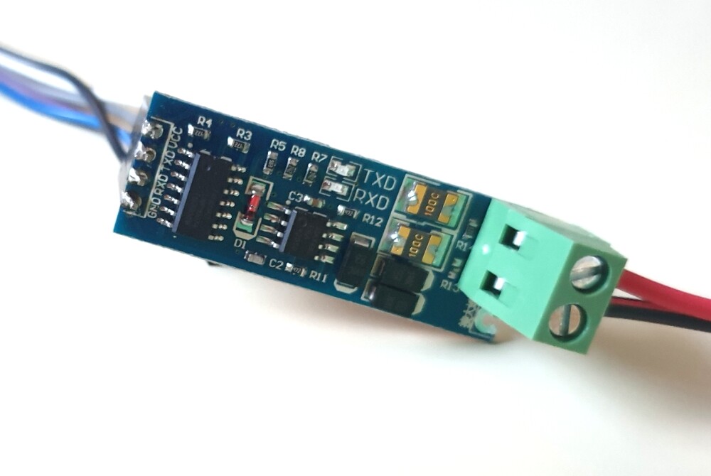
That doesn't have to sustain. Use a RS485toCMOS adapter instead.
That seems to show that your hardware is working as you expected it. Another possibility for the problems may be a wrong baudrate or wrong parity. If you were able to configure these values on the PC correctly you should have the correct values. Did you use the right ones in your sketch?
You are right about the 5V Vcc. The information on the page is incorrect. At first, I used 5V for all the testing I have done. Then I came across the page above. I just tried 3.3V and the Rx led lit up when the EV charger sent a request. This made me believe it worked. But the Serial Monitor app did not show any new coming messages.
So, I switched back to 5V and re-tested it. This time a message was detected.
I cannot find any hint that this board takes 3-30V as power source.
There are no schematics linked so it's pure guessing what components the board carries. It's cheap Chinese stuff, so it may work or it may not. And don't trust the vendor information as they link to the MAX485 datasheet and that series of chips isn't compatible with 3.3V signals. Maybe that larger chip on the board is a level converter but I don't see a voltage regulator, so too much guessing. If it doesn't work out of the box as expected, assume it contains fake chips.
That's on the PC, so what does that show?
Why's that a success? I thought the messages always showed up on the PC (see post #1).
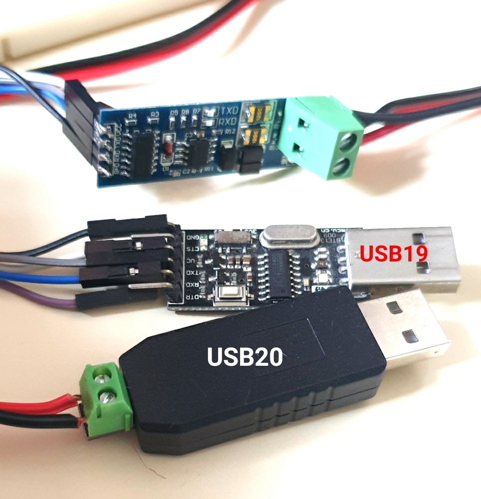
I ordered a USB-RS485 dongle and just received it today. So, I did some testing and it was very strange, beyond my knowledge.
In my first post, I captured the message through the RS485-TTL board + the TTL-USB board ("USB19"), using my notebook. Later, I did all the tests on my PC with my EV charger laying nearby.
I chain 2 USB-RS485 devices. USB19 is using RS485-TTL-USB boards while USB20 is the RS584-USB dongle.
Before this time, I had done all the testing using USB19 hardware. The YAT capture always showed:
01h 03h FCh 02h 00h 01h 15h 9Ah
I tested the RS485-USB dongle and it showed the same result. Then I plugged both 2 USB altogether, showing USB19 and USB20 in the YAT program.
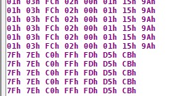
But the led on the RS485-TTL board stayed lit up and the board seemed to be frozen. So, I unplugged the two units out and tested only one of them at a time. The results become strange, as in the picture.
The upper part is from the RS485-USB dongle (USB20). The lower part is from the RS485-TTL-USB (USB19). I repeated the test 3-4 times and the results were the same. I don't know what happened to the hardware, or software-wise.
And this was the situation/problem I found when I used my Wemos D1 read messages from the RS485-TTL-USB. The numbers are different.
But I retested them with RTU-Slave code, from the modbus-esp8266 library, on my Wemos D1. It was so weird that both of them reported the correct message values !!
My RTU-Slave only contains 0x78 on the 0xFC02 Hreg. The reply was correct.
#define MODBUSRTU_DEBUG 1 // ModbusSettings.h
I think I know where the problem is. It looks like the power supply problem using old jump wires (Dupont). Some of them have rust on pins, and my Wemos D1 is also aged 4 years, rarely used. Its connectors might be not clean.