Simple Modbus Slave RS485 Invalid CRC problem

Hello,
I'm configuring my RFID readers system.

I have 3 Arduinos (slaves), each of them has own RFID reader, and I would like to connect them via Modbus RS485 with my PLC driver Delta DVP 14SS2 (Master).
PLC will contact each Arduino sequentially every second and use only 03 Modbus function to read the register which will store RFID tag number during it's in RFID reader range.

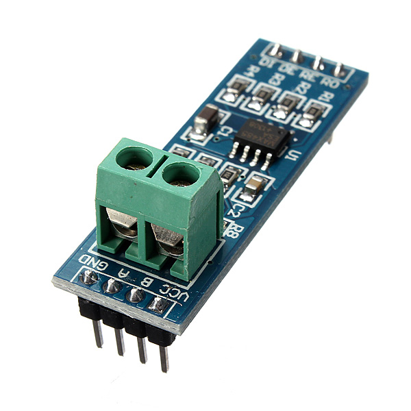
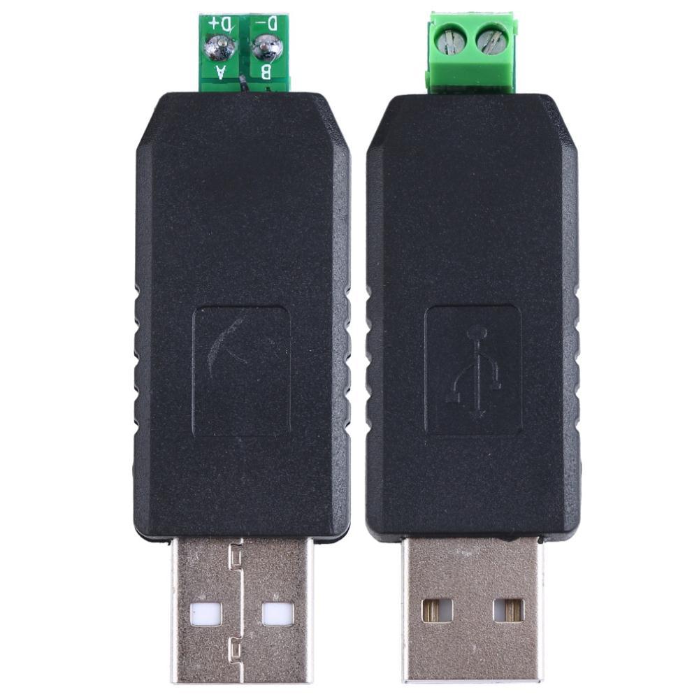
Currently I'm trying to connect only one Arduino (without RFID capability) with my PC through the USB FTDI RS485 converter with QModbus software and I'm having a problems.
For now I'd like to read one Modbus register. When the Arduino is connected to PC via USB cable and I choose in QModbus Serial Port of Arduino it receives correct data from the selected register without any problems (screen nr 1).
After I disconnect the USB cable, try to connect to Arduino via Serial Port of my USB FTDI RS485 converter, send 03 Modbus function read request I'm getting the CRC error 'Slave threw exception "Invalid CRC" or function not implemented" (screen nr 2). In Bus monitor I have two additional bytes. One on the beginning of the answer (00) and the second one on the end, also 00.

What I've already tried:

  1. I used few libraries but for me works only ModBusRTU and SimpleModbusSlave. Mentioned CRC problem occurs with both libraries.
  2. Changed Serial Port settings like Parity etc. I always remeber to set it correctly.
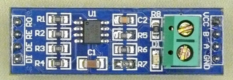
  3. Added the 120 Ohm resistors on the ends of RS485 bus.

Maybe it's the converter problem? Modbus seems to work properly via Serial port of Arduino via USB connection.

RS485_slave.ino (892 Bytes)

SimpleModbusSlaveArduino.ino (4.27 KB)

Hello, is anybody out there who can help me? :slight_smile:

duff121:
For now I'd like to read one Modbus register. When the Arduino is connected to PC via USB cable and I choose in QModbus Serial Port of Arduino it receives correct data from the selected register without any problems (screen nr 1).
After I disconnect the USB cable, try to connect to Arduino via Serial Port of my USB FTDI RS485 converter, send 03 Modbus function read request I'm getting the CRC error 'Slave threw exception "Invalid CRC" or function not implemented" (screen nr 2)

Hi , I have the same problem :confused: :confused: :confused:
Do you solve it ?

Please provide a link to the exact product of USB RS485 converter you're using. The schematic of the cable and how the DE pin is signaled might be essential. It might be necessary to bring the RS485 bus to a defined state if no driver is enabled. I use one set of resistors on the bus to pull the two data wires up/down.

Edit: The ModBus message CRC is OK if the leading and trailing zero bytes are removed.

I see why the "SimpleModbusSlaveArduino.ino" doesn't work. The serial interface is configured to 8N2 while the PC uses 8N1. From which sketch do the two screenshots originate?

Hi this is my circuit :

and when i coennect it to my laptop via RS485 to USB Converter(com7) i have this result on Qmodbus software:

But if i Connect Arduino via USB Adapter to my laptop and choose USB Arduino (COM6) for Serial port
I have this result , in this case everything work fine and without any error or problem

i use same program for arduino in both case , This is the arduino code for test:
my modbus library for arduino is Modbus-Master-Slave-for-Arduino

/**
 *  Modbus slave example 3:
 *  The purpose of this example is to link a data array
 *  from the Arduino to an external device through RS485.
 *
 *  Recommended Modbus Master: QModbus
 *  http://qmodbus.sourceforge.net/
 */

#include <ModbusRtu.h>

// assign the Arduino pin that must be connected to RE-DE RS485 transceiver
#define TXEN	2 

// data array for modbus network sharing
uint16_t au16data[16] = {
  3, 1415, 9265, 4, 2, 7182, 28182, 8, 0, 0, 0, 0, 0, 0, 1, -1 };

/**
 *  Modbus object declaration
 *  u8id : node id = 0 for master, = 1..247 for slave
 *  u8serno : serial port (use 0 for Serial)
 *  u8txenpin : 0 for RS-232 and USB-FTDI 
 *               or any pin number > 1 for RS-485
 */
Modbus slave(1,0,TXEN); // this is slave @1 and RS-485

void setup() {
  slave.begin( 9600 ); // baud-rate at 9600
}

void loop() {
  slave.poll( au16data, 16 );
}

So What's the problem ?

So What's the problem ?

You don't have links to the hardware you're using, so I have to guess about the problem. It might be that the bus doesn't have a defined state if none of the devices is sending (no bus driver is activated). I have pull up/down resistors (only once in the whole bus) to define a state in this case. It might be that your RS-485 module includes this but I simply don't know.

It would explain why the transfer of the acutal message is correct but around the message you receive random data.

Do you have a link to the module you're using?

This is a module for TTL<=>RS-485 : MAX485 module - TTL to RS-485 module

This is a module for RS-485<=>USB :USB to RS485 Module (CH340)

The USB-Module seems to be a pretty normal USB2Serial with a RS-485 driver. The TTL-to-RS485 module doesn't provide a schematic (at least I couldn't find one) so I tried to find out how it's wired from the photos.

R1 to R4 seems to be directly connected to DI, RO, RE and DE, so they're just for chip safety. C1 or C2 is the decoupling capacitor for the MAX485. R8 is probably the current limiting resistor for the LED. I don't know where the LED is connected to and what the second capacitor is used for. I also cannot find out what connects to resistors R5 to R7. Can you try to find that out?

TTL-to-RS485 module schematic : Link To the Site for Details

and a Top view of Module :

At least on the picture in your last post the resistors R5 and R6 are 10kΩ and not 20kΩ but that make little difference. Using this module the bus gets set to 2.5V without any driver active with a difference of A and B of only about 30mV which is below the sensitivity of an RS-485 receiver. To get a good result you should use a pull up/down resistors (what R5/R6 are doing) of 600Ω - 1kΩ, at least in my experience. If you ask the RS-485 line termination calculator it says the resistors should be about 540Ω. Because the USB adapter has such resistors (a bit too big, 2.2kΩ) it might work without is but I would install another 2.2kΩ to get better results. If you have the possibility, measure the line with a scope.

Also remove the terminating resistor you have in your schematic(SCH.png) on the Arduino side because that is already on the board. If an Arduino board is not at an end of the bus you should desolder the resistor R7 from the board because that's the termination which should exist only at the ends of the bus.

impluse:
Hi , I have the same problem :confused: :confused: :confused:
Do you solve it ?

Yeah, problem solved. It was very simple. My mistake.

DE + RE pins of TTL<=>RS-485 converter wasn't properly connected to the Arduino digital pin. Since I've connected it reliably to my Arduino everything works like a charm.

So I don't believe that Modbus Master/Slave library works on newer based hardware.

The UNO and the Mega2560 are about the same generation of Arduino hardware. You might have to explain what does not work and how you set things up and what code you used.

You didn't describe why you use two Arduino UNOs to provide that setup.

From you description I guess that you're not using the hardware serial interface but that crippled SoftwareSerial. Don't use SoftwareSerial if you need any other hardware part that relies on interrupts to work.
Getting the wiegand protocol and the ModBus library to work on one UNO is not a big deal if you use the hardware and not a badly coded software emulation.

Please post a wiring diagram of your setup and the code you're using. I'm quite sure the problems you have with the Mega2560 are hardware (wiriing) related and not a software problem.

This is the code that does not work because both includes use pins 2 and 3 for communication:

pin 3 is not used by ModbusRTU in that example. Why do you connect the TXEN to pin 2? You have plenty of other pins to connect that to and you're free in the software to define any pin for that function.

I understand that the wiegand protocol is simpler to implement if you can use the hardware interrupts and don't have to fiddle with pin change interrupts, so I would leave that functionality on pins 2 and 3.

void loop() {
   slave.poll( au16data, 16 );
   Wire.begin(SlaveDeviceId);
   Wire.onReceive(receiveEvent);//interrupt handler for incoming message
   if (newReceiveEvent == true)
    {    Serial.println("Got some data");

    for (byte j = 0; j < 2; j++)
    {
      Serial.println(receiveInts[j]);
    }
    newReceiveEvent = false;
    }
    if (errorEvent == true)
    {
    Serial.println("I2C Receive Error");
    errorEvent = false;
    }
    au16data[0] = receiveInts[1];
    au16data[1] = receiveInts[0];
    delay(500);
 }

It's a bad idea to have an RS-485 driver connected to the serial interface and while listening for some ModBus commands print any debugging garbage to that interface. Either use that interface for ModBus or for debugging. I suggest the former.

Also remove that delay(500) call because it ruins the ModBus interface response time.

The Wire.onReceive() call should be in the setup() routine (needs to be called only once) as should be the Wire.begin().

In that code you also use Wire.readBytes(), which uses timedRead() to get it's bytes. Keep in mind that the timeout feature of that method is not available inside the receiveEvent() function (interrupt context).

void loop() {
	if(wg.available())
	{
	  Wire.begin();
    Wire.beginTransmission(SlaveDeviceId);
    Wire.write((uint8_t*)&sendInts, sizeof(sendInts));
  	Serial.print("Wiegand HEX = ");
		Serial.print(wg.getCode(),HEX);
		Serial.print(", DECIMAL = ");
		Serial.print(wg.getCode());
		Serial.print(", Type W");
		Serial.println(wg.getWiegandType());  
    byte myArray[4];
    long reader1 = wg.getCode();
    myArray[0] = (reader1 >> 24) & 0xFF;
    myArray[1] = (reader1 >> 16) & 0xFF;
    myArray[2] = (reader1 >> 8) & 0xFF;
    myArray[3] = reader1 & 0xFF;
    sendInts[0] = (reader1 >> 16) & 0xFFFF;;
    sendInts[1] = reader1 & 0xFFFF;;
     Serial.println(reader1 & 0xffffffff);
    Serial.println(sendInts[0]);
    Serial.println(sendInts[1]);
     Serial.println(reader1 & 0xffffffff);
    delay(1000);
    Wire.endTransmission();    // stop transmitting Serial.println(" Reader 1 High Part");
	}
}

In this code Wire.begin() should be in the setup() routine too.

I don't understand why you have the delay() there. You know that nothing is sent over the I2C until the Wire.endTransmission() is called, do you? The way the code is currently structured you're sending the data of the previous wiegand read when the next chunk of data arrives. I guess that is not what you wanted to achieve.

The version of "Two_Arduino_Wiegand_End.ino" you posted does not compile (missing brace) and still has Wire.begin() in the loop() instead of setup() but the rest should work.

Both of these include project seem to operate in a similar fashion. they are both slaves waiting for pin change on two pins.

The wiegand implementation you currently use does not use the pin change interrupt but the hardware interrupt pins D2 and D3.

With only 3 x pin change interrupt vectors they would need to be time shared. (Time division multiplexed)

I don't see why you need to have a time sharing or time division multiplexing here. You can have both functionality implemented, you just have to make sure that the interrupt routines are as short as possible, moving all time consuming stuff to the loop() function.

You were right. All I had to do to get it working was to move the TXEN pin. It works great now. I got the Wiegand to Modbus protocol converter working fine on a single Arduino. Then I enhanced it by writing the door status and controlled the beeper on the RFID reader. So its job done for that project. I did find a way of using the shield by removing the jumper and putting a link over to a spare GPIO pin.