I have put a couple of instructables up that may of be some interest:
This one includes a faster font drawing graphics library:
I have put a couple of instructables up that may of be some interest:
This one includes a faster font drawing graphics library:
I am about to pull all my hair out (and I dont have a lot to start with)!
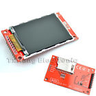
I have a 2.2 TFT as per most of the videos and pictures displayed here. (2.2 inch 2.2" SPI TFT LCD Display module 240x320 ILI9341 51/AVR/STM32/ARM/PIC) as per picture attachment.
I have it connected up to a Mega 2560.
Wiring:
PIN MEGA CD4050 2.2TFT
SCK 52 YES SCK
MOSI 51 YES MOSI
MISO 50 NO MISO
D/C 4 YES D/C
RST 5 YES RST
CS 11 YES CS
So, I have a level converted between the Mega and the 2.2 TFT on all pins except the MISO pin.
I have tried more libraries than I care to count. Most notable being UTFT, TFT, TFTV2, ADAFRUIT_ILI9340, ADAFRUIT_ILI9341.
If I run the TFT example TFTDisplayText with only these changes:
#define cs 11
#define dc 4
#define rst 5
I get text coming up on my display, all be it reversed, the screen flickering white and only occupying 25% of the screen. I know this is because that library was developed for a different display so ... expect issues. The reason I mention it however is, I assume that based on the fact that it is working here, that my wiring is not wrong. I might be wrong on this assumption.
ALL the other libraries give me a white flickering screen with nothing else happening.
I desperately need assistance on this.
If anyone out there has managed to find a solution, please ...
I must use SPI to access the display. I have not even started to engage the device on the SD card yet so this will be the next challenge.
Your assistance is appreciated.
DWaterford:
Your assistance is appreciated.
The TFT library is for a different display chip which will not initialise the display correctly.
As you have surmised the reversed text suggests the connections are right.
You need to try a library with ILI9341 driver again as that is the only one that will configure the display correctly.
You could try the library with the ILI9341 driver that I put together as detailed here.
K5CZ:
I moved the wires from the D4-D7 to D48-D53 and now do experiments with library Adafruit_ILI9340 - it works fast and fine.Part of definition/wiring:
#define _cs 53
#define _sclk 52
#define _mosi 51
#define _miso 50
#define _dc 49
#define _rst 48
// Using software SPI is really not suggested, its incredibly slow
//Adafruit_ILI9340 tft = Adafruit_ILI9340(_cs, _dc, _mosi, _sclk, _rst, _miso);
// Use hardware SPI
Adafruit_ILI9340 tft = Adafruit_ILI9340(_cs, _dc, _rst);
Before that I tried UTFT library, but it did not work. Although wiring is the same and the definition in program is obvious:#define TFTcs 53
#define TFTsclk 52
#define TFTmosi 51
#define TFTdc 49
#define TFTrst 48
UTFT myGLCD(TFT01_22SP,TFTmosi,TFTsclk,TFTcs,TFTrst,TFTdc);//SERIAL_DATA_INPUT_SDI_MOSI,SERIAL_CLOCK_SCLK_SCK,CHIP_SELECT_CS,RESET_RST,REGISTER_SELECT_RS_DCSo question is: what is wrong? PS: UTFT works on my Mega 2560 with 1.8" TFT / ST7735S (identical wiring)
Thanks for this, 2 minute job to get LCD working after removal from anti-static.
Grab the adafruit librarys off github, grab the IL9340 example and edit the above defines in instead of the existing ones. done.
I connected the backlight to 3.3v via a 47ohm though, I am not prepared to thrash my Due board by driving the backlight array with a single PWM pin. Without a backlight on this display you will see NOTHING. I thought a hint of display but no.
So the LCD is powered by 5v currently but I hear the little solderable jumper by the regulator can be used to drive it from 3.3v instead. Not tried it yet.
I just thought I'd add that I have managed to get an ILI9340 LCD working without a level shifter. I used 1K resistors between all pins except for VCC, GND and LED. Not sure if I'm doing slight damage this way but it seems to work well for me.
I have a problem. Nothing happens with the display except I cant turn on the backlight with connecting LED pin to voltage. ![]()
So parts that I'm using.
Converter:
http://www.ebay.com/itm/281619636885
and Arduino Mega 2560 board.
So the wiring follows.
From arduino
3.3v goes to the Converter's 3.3v on the low side and also to LCD VVC pin.
GND goes to the Converter's GND pin on the low side and also to LCD GND pin.
Then all the wiring is thru converter except the MISO which is direct to arduino. All others go from arduino to Converters High pin and then from Low to LCD pin. For each wire seperate High and low ofcourse.
So:
CS 10
DC 9
RST 8
MOSI 51
SCK(SCLK) 52
MISO 50 (direct to arduino)
I don't know about LED. I put it on 3.3v but as I know it doesn't really matter?!?
So as far as I know wiring is correct?!
Can you tell me which code (library) to run. exemple. I have so many different libraries and none of them works.
Thanks
I personally would wire the LED directly to 3.3 or 5V.
which lib do you use?
Im using ILI9341 from github
could you please post the complete code in code tags?
Using Arduino Mega and lib from
Code is the same as the graphic test just the first part which is copied is different where pins are defined.
#include "SPI.h"
#include "Adafruit_GFX.h"
#include "Adafruit_ILI9341.h"

// For the Adafruit shield, these are the default.
#define TFT_RST 8
#define TFT_DC 9
#define TFT_CS 10

#define TFT_MISO 50
#define TFT_MOSI 51
#define TFT_SCK 52


Adafruit_ILI9341 tft = Adafruit_ILI9341(TFT_CS, TFT_DC, TFT_RST);

void setup() {
  Serial.begin(9600);
  Serial.println("ILI9341 Test!");

  tft.begin();

  // read diagnostics (optional but can help debug problems)
  uint8_t x = tft.readcommand8(ILI9341_RDMODE);
  Serial.print("Display Power Mode: 0x"); Serial.println(x, HEX);
  x = tft.readcommand8(ILI9341_RDMADCTL);
  Serial.print("MADCTL Mode: 0x"); Serial.println(x, HEX);
  x = tft.readcommand8(ILI9341_RDPIXFMT);
  Serial.print("Pixel Format: 0x"); Serial.println(x, HEX);
  x = tft.readcommand8(ILI9341_RDIMGFMT);
  Serial.print("Image Format: 0x"); Serial.println(x, HEX);
  x = tft.readcommand8(ILI9341_RDSELFDIAG);
  Serial.print("Self Diagnostic: 0x"); Serial.println(x, HEX);

  Serial.println(F("Benchmark                Time (microseconds)"));

  Serial.print(F("Screen fill              "));
  Serial.println(testFillScreen());
  delay(500);

  Serial.print(F("Text                     "));
  Serial.println(testText());
  delay(3000);

  Serial.print(F("Lines                    "));
  Serial.println(testLines(ILI9341_CYAN));
  delay(500);

  Serial.print(F("Horiz/Vert Lines         "));
  Serial.println(testFastLines(ILI9341_RED, ILI9341_BLUE));
  delay(500);

  Serial.print(F("Rectangles (outline)     "));
  Serial.println(testRects(ILI9341_GREEN));
  delay(500);

  Serial.print(F("Rectangles (filled)      "));
  Serial.println(testFilledRects(ILI9341_YELLOW, ILI9341_MAGENTA));
  delay(500);

  Serial.print(F("Circles (filled)         "));
  Serial.println(testFilledCircles(10, ILI9341_MAGENTA));

  Serial.print(F("Circles (outline)        "));
  Serial.println(testCircles(10, ILI9341_WHITE));
  delay(500);

  Serial.print(F("Triangles (outline)      "));
  Serial.println(testTriangles());
  delay(500);

  Serial.print(F("Triangles (filled)       "));
  Serial.println(testFilledTriangles());
  delay(500);

  Serial.print(F("Rounded rects (outline)  "));
  Serial.println(testRoundRects());
  delay(500);

  Serial.print(F("Rounded rects (filled)   "));
  Serial.println(testFilledRoundRects());
  delay(500);

  Serial.println(F("Done!"));

}


void loop(void) {
  for(uint8_t rotation=0; rotation<4; rotation++) {
    tft.setRotation(rotation);
    testText();
    delay(1000);
  }
}
Hi,
I am using Adafruit library and the display works. But I would like to load a bmp file from the SD but I am not sure about the wiring.
The SD_CS that is referenced by Adafruit library is the pin close to the SD? Am I supposed to solder these pins that are close to the SD in order to use these pins or they are useless?
Users of the ILI9341 based displays may be interested to know that my TFT_ILI9341 library and example sketches are now available on Github.
Further info on library can be found here.
Typically performance is 3 to 6 times faster that the standard Adafruit GFX library and up to 20 times faster than UTFT. Full 320 x 240 screens are cleared in 174ms, raw images (320 x 240) can be pulled off an SD Card and drawn within 405ms using an optimised Sdfat library. So the graphics drawing performance is now about as good as it is going to get on a humble 16MHz AVR Arduino!
CelticHarp:
I am using Adafruit library and the display works. But I would like to load a bmp file from the SD but I am not sure about the wiring.
I have mine wired like this to make spitftbitmap.ino display the dog image. Wire SD_MOSI to LCD MOSI, SD_MISO to LCD MISO, and SD_CLK to the LCD CLK. Wire SD_CS (chip select) to a level shifter then Uno pin 4
LCD pins  SD pins Uno pins
--------  ------- --------
          SD_CS   (level shift) 4
SDI/MOSI  SD_MOSI
SDO/MISO  SD_MISO
SCK       SD_CLK
          F_CS not connected
Helo
I use adruino micro clone from E-bay and libary from user rowboteer and 2.2 SPi display with ILI9341.
For convert 5V to 3.3 I use 4050 logic converter, shematic is similar to this

with flat

Well, your 4050 circuit looks absolutely fine. Why use external 3.3V rather than the 3.3V pin on your Micro?
What do you expect people to see from your videos?
You cannot see the wiring.
If it works with single wires, it will work with a ribbon. Providing you connect the same points. i.e. you have correct wiring.
It is a mystery why people choose to use level shifters when it would be simpler to just run the Micro at 3.3V
David.
David thank you for fast response. I use extrenal 3.3V beacuse sparkfun promicro doesent have it. And I use 4050 for severval reasons:
I upload video so you can see how display work on flat and how work on single wires
I checked few times is conection good with flat cable and I can't find what is wrong. I don't know what to do next?
You can run an AVR at 3.3V and 16 MHz and I bet that it will work 100%. Fine for hobbyist projects, unwise for commercial products.
You can modify your Micro to run at 3.3V fairly easily.
Of course, you may have a reason for 5V. In which case you have proved that the CD4050 provides correct levels for the display and SD.
There is clearly a wiring difference between your ribbon and the individual wires. Post a clear stationary photo of the wiring. Then other eyes might spot your error.
A video of a white screen is not very helpful. You might just as well write one sentence in plain text.
David.
David i didn't know that micro can work on 3.3 V conected to USB, thank you for that information ![]()
Here is the news, i don't know why and how but now the LCD work
even with a 40 cm long flat cable, i didn't change anything, only tried to upload some others sketch but at the end I upload that old sketch same as in video with white screen.
Thank you David for all your help
I am horrified by your hardware "arrangement".
Buy the bigger size of protoboard and a pack of female header strips.
Solder the required lengths of header to match your Nano and the Display.
Add the relevant wiring connections with proper soldered joints.
3.3V operation means 0R inter connections. 5V operation means 1k0 series resistors.
Then you can mount the TFT display and your Nano / Micro with good reliable connections.
I make up "shields" to receive the TFT display. Then plug them into FRDM, NUCLEO, DUE, ... boards.
That 40-way ribbon is nothing more than a nuisance.
David.
hehe i can't yust buy like that protoboard, in my country there is no electronic store and the only option is ebay and that mean I must wait it for 30-40 days, I ordered biger protoboard but it didn't came yet. So i must use what I have at home :(, and I am a realy new in electronis,slodering etc. so my project are relaly not for
exposition ![]() for now it only mather does it work.
for now it only mather does it work.
I didn't understand what you said about that resistor and operation voltage?
SHIELD doesn't help me beacuse I make board comp for my car, so display must be in cluster and arduino somewere under dash beacuse there is not enough space in instrument cluster
I realy appreciate your help and advice ![]() perhaps my sentance sounds rough beacuse my bad english,but I am realy gratefulness for your help
perhaps my sentance sounds rough beacuse my bad english,but I am realy gratefulness for your help
