Servo causing positive voltage spike

I have a 3.7V lipo powering an ESP32.
I also have a boost converter that outputs 5V (https://www.amazon.com/dp/B091CRCZ65

When I command a new position:

  1. PWM changes
  2. battery current draw, so sags
  3. Position is reach, so battery recovers
  4. 5V supply overshoots???

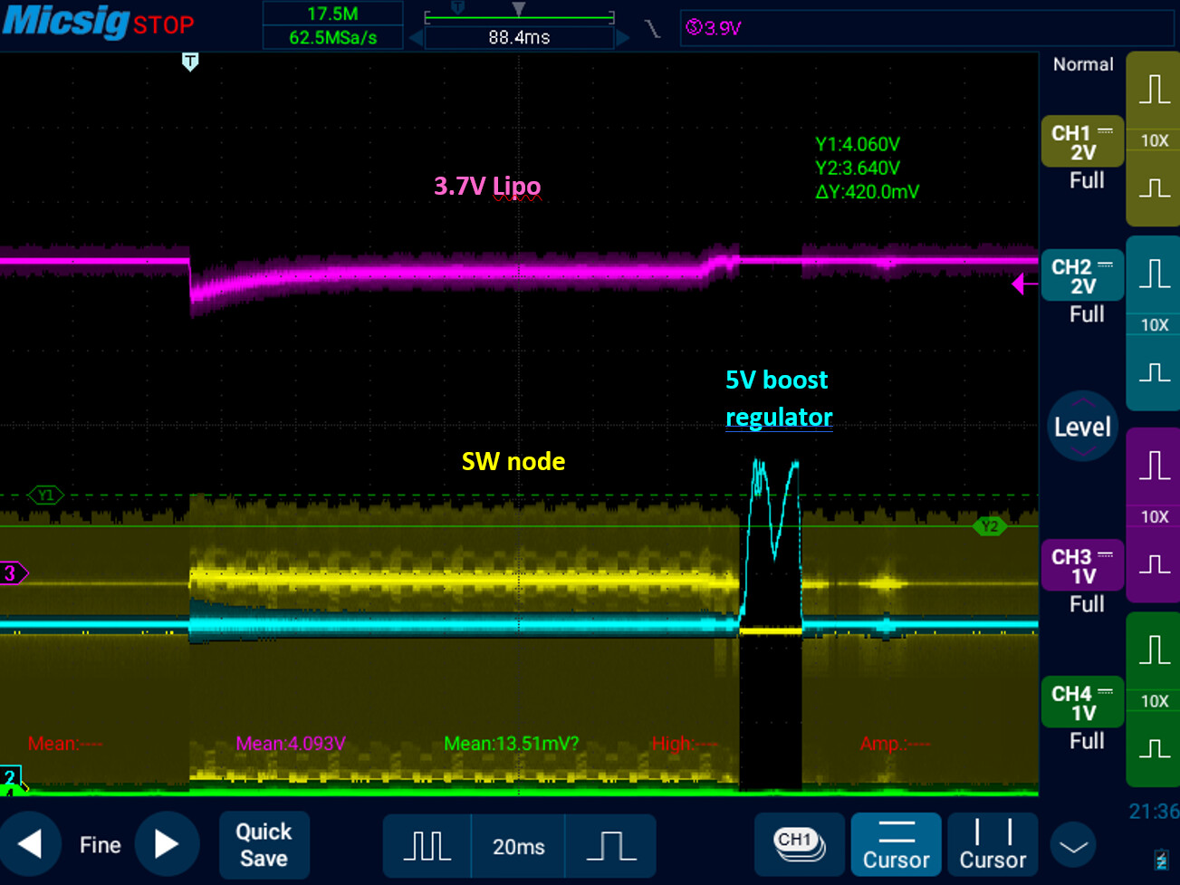
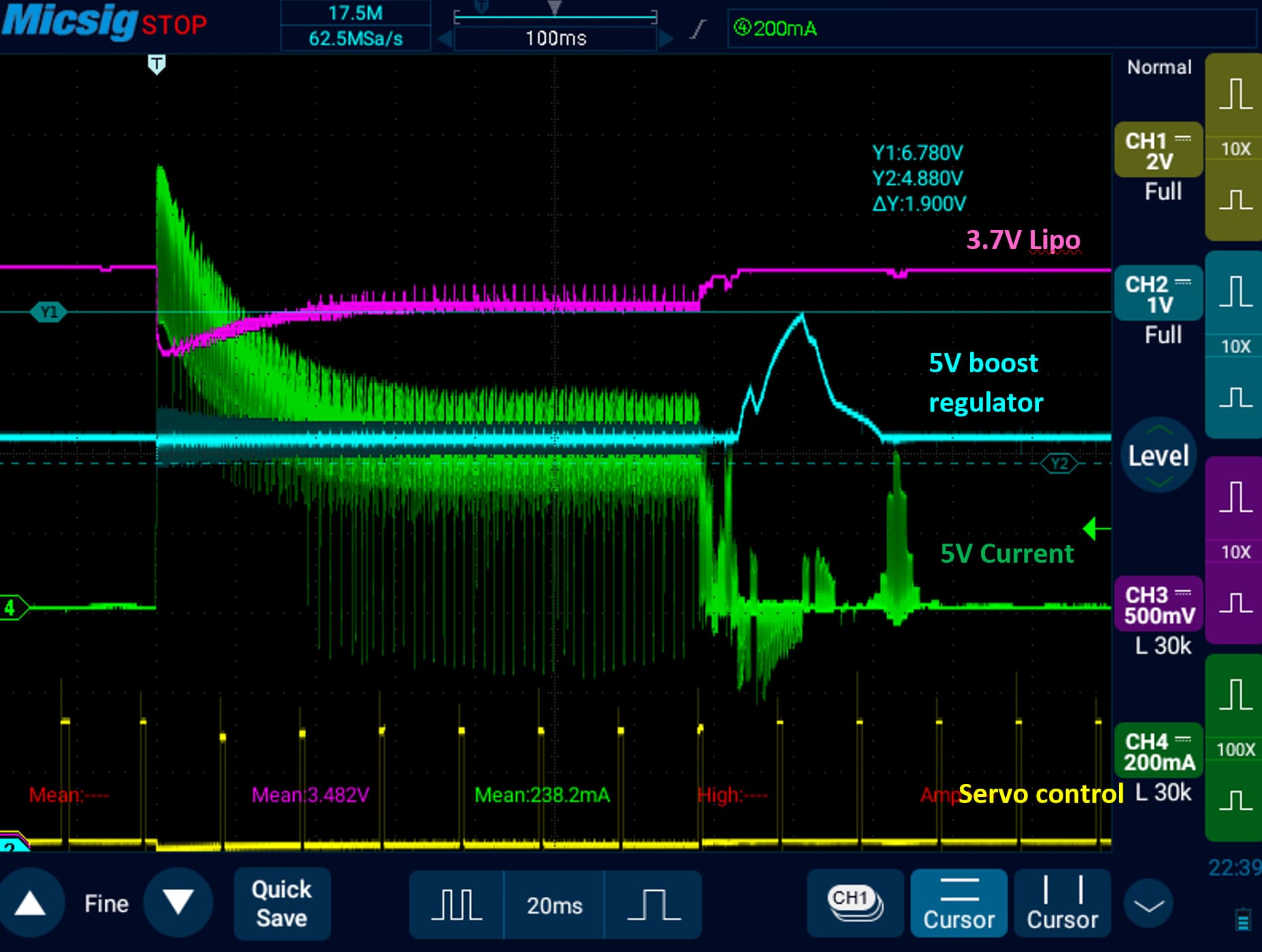
What is going on?? The boost converter stops switching, as it realizes the 5V output is too high.
But, the output keeps rising.... I added an addition 100uF 10V X5R 1206 capacitor across the output and input of the boost converter, but it still does the same thing.

Edit, I also measured with a 0.1Ohm shunt on the servo ground line, that the current does go a tiny bit negative during the time when 5V overshoots.

Nothing strange, in general. If You post a link to the servo datasheet we will know more. 1 Amp output might be too little for that servo.

It's a MG90S I bought on Amazon.

Negative current is normal? Here is a scope shot showing the negative current corresponding to when the 5V rail overshoots.

Edit:
Is it safe to have the 6V rail hit 7V?

Hi, @h2e
Can you post some images of your project?
Please include where you have connected your scope probes.

Can you post a link to data/specs of your DC-DC converter?

Thanks.. Tom.. :smiley: :+1: :coffee: :australia:

I think for any useful response you will need to provide a schematic.
How to make a schematic you can post. - Using Arduino / Introductory Tutorials - Arduino Forum

However the physical layout is also relevant so a photo of your setup please

1 Like

Take your current measuring resistor out of the circuit, I think is is causing about 1/2 of your overshoot.

  • a current moving though a wire creates a magnetic field
  • a magnetic field moving past a wire creates a current
  • the motor contains coils of wire. a current moving through a coil of wire creates a large magnetic field
  • when you cut off that current, the magnetic field collapses inward
  • the inward collapsing magnetic field is a magnetic field in motion. it creates a current surge in the coil.
  • the voltage of the current surge is not related to the voltage that created the magnetic field. the voltage of the current surge is related to the rate of collapse of the current

you need a snubber diode, AKA a flyback diode, AKA a commutating diode

these names describe the function of the diode, not the name of the diode. any junk box or Radio Shack diode should work. connect it across the positive and negative terminals of the motor, anode to negative and cathode to positive, so it absorb the reverse current surge caused by the magnetic field collapse.

I initially did not have the current sensing element; adding/removing it made no appreciable difference.

The circuit is extremely simple.

Given it is a servo, and it moves in both direction, it must have an H-bridge circuit and intrinsic diodes...

But I think it makes sense now to me.
When it is moving fast to one position, current will flow through two switches Q1 and Q4 in red.

When it reaches the position, the servo could do two things...

  1. Turn off only one of Q1 and Q4. This will let it "freewheel". For example current through Q1 and D3, or Q2 and D4.
  2. Turn off all switches. Then, current will flow through D2 and D3, and charge the 5V rail.

It seems the servo I have does (2). Not sure why though.

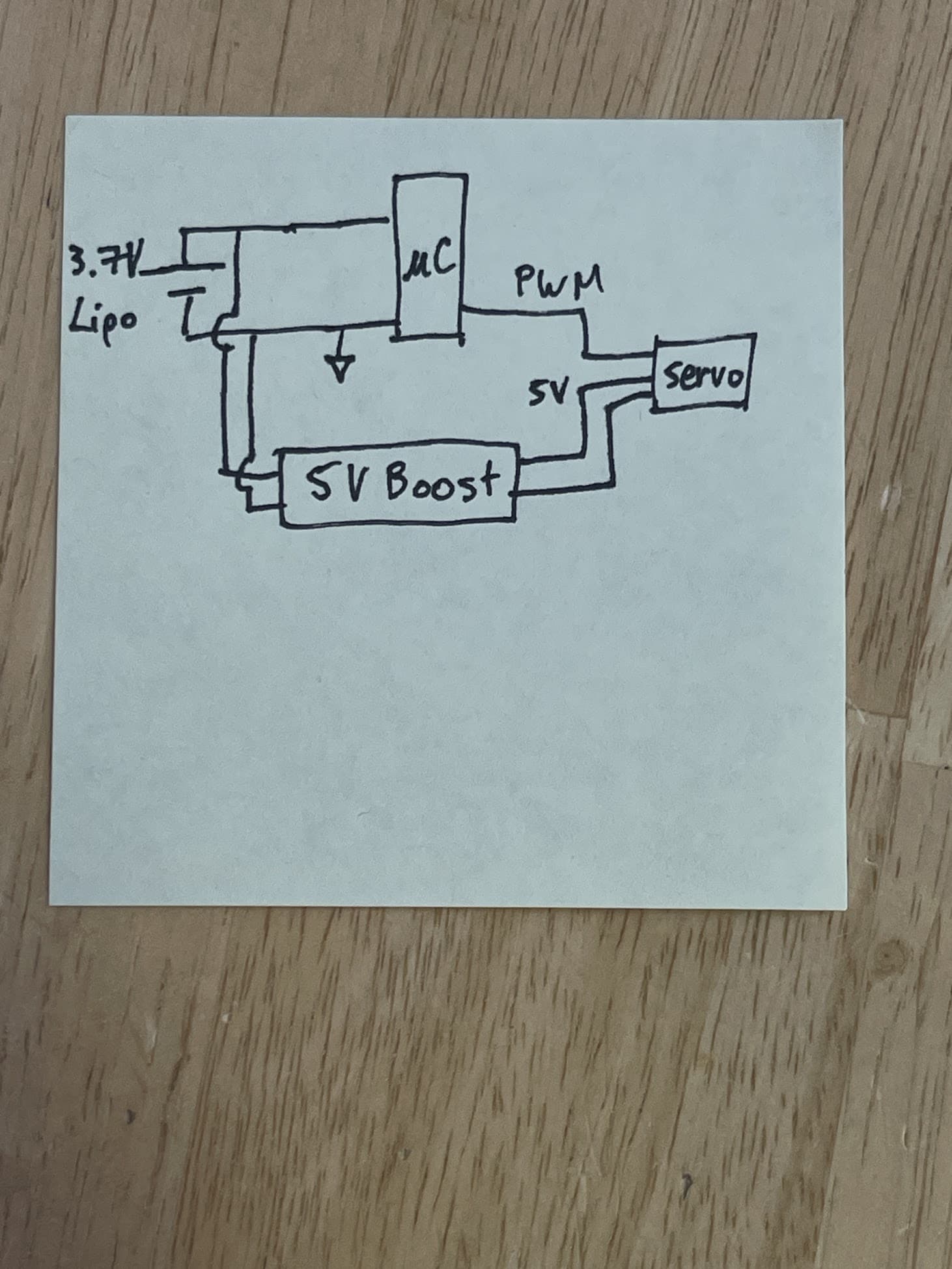
The boost converter and the battery combination is inadequate to handle the start/stall current of the servo, and the circuit lacks proper power supply decoupling.

Due to boost converter inefficiency, 5W output to the servo requires about 6W input from the battery, or 6W/3.7V = 1.6 Ampere battery current draw.

No surprises at all.

Hive you provided a link so we know WHICH servo you have?

Actually 3 things.
It's a servo, so the motor stays energized when it reaches the commanded position.
That would imply that the H bridge is still ON.

Hi, @h2e
Have you verified that the gnd input and the gnd output of the DC-DC converter are connected?

Thanks.. Tom.. :smiley: :+1: :coffee: :australia:

This topic was automatically closed 180 days after the last reply. New replies are no longer allowed.