I am unable to set up my boards in the Arduino cloud. I am perhaps not too surprised that the clone Nano with CH340 on board is not detected, but I didn't get the 'unknown board' dialogue to be able to select the Nano.
I then tried setting up this clone Nano manually got given an ID and key, but no instructions on what to do with them? I am coming to this ( IoT cloud) as an absolute newbie which is supposed to be the target audience?
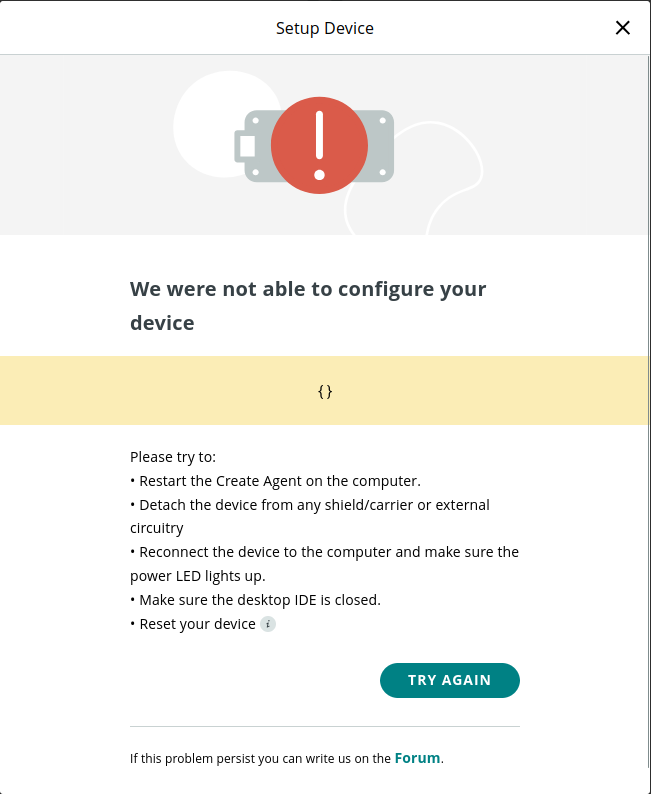
What did surprise me was that I couldn't set up the genuine Nano RP2040 I tried next. This does get detected and I can proceed through the configuration process. The Nano RP2040 goes into bootloader mode and I get prompted to give it a name, but after that it fails with the message "We could not find any Arduino device":
A bit of Googling found another thread on the forum which suggested a double-tap on the reset button should do the trick but so far I have been unable to make this work either.
It is unfortunate that this step is not mentioned so a newbie like me is now stumped. At the very least it might have been helpful if it had been mentioned in the pop-ups that come up during configuration and I would like to request that this information be added please. Unfortunately that same thread also mentioned that the process is "unreliable at best" so perhaps I need to persevere a few times?
If anyone can provide any insight it would be appreciated:
Firstly, is it even possible to set up the clone Nano? Does it update from the cloud via the agent - or do I need to use a device with WiFi so that it can connect directly to the Internet?
Secondly, I would appreciate any advice on exactly when I need to double tap the reset button? The other thread said before configure, but so far this has not worked.
The Nano is not supported for use as an Arduino Cloud IoT Device. This actually isn't because it is a clone. The "I" in "IoT" stands for Internet, meaning that the board must have the capability to connect to the Internet in order to be used as an IoT Device. The classic Nano does not have any network connectivity capability. It is true that you could connect an external module to the board to achieve such a capability, but then you would also run into the problem that the classic Nano's ATmega328P microcontroller has relatively limited amount of memory and the network communication aspect of any IoT Thing sketch requires more memory than it provides, even before adding any additional code for the specifics of your project.
You can learn which boards are supported from this section of the Arduino Cloud documentation:
Please note that, although you can't use it with the IoT component of the Arduino Cloud platform, you can use the Arduino Cloud Editor component to create, compile, and upload non-IoT sketches with the clone Nano board, just as you would do with Arduino IDE:
ptillisch, thank you. That does make sense and I guess that I had come to that conclusion but I appreciate your confirming it. I found a couple of threads about connecting clone Nano boards so wanted to give it a try, but that would indeed only make sense for using the online IDE and explains why there were no IoT examples, as they wouldn't apply. Setting it up as a device manually and then selecting the board from the online sketch editor as one does within the desktop IDE, does allow it to be programmed in that way though.
On the other hand, this does not explain why I can't get my Nano RP2040 Connect board to work. Looking through the linked information, it is one of the supported boards and whereas the article mentions setting up ESP boards, it doesn't appear to mention RP2040/RP2350 based boards. I believe that the thread I mentioned in the OP is probably correct when it talks about double-clicking the reset switch, but it probably has to be done at the correct moment. I have tried several times with different timing permutations, but still haven't managed to get it added as a device on the ioT cloud. If I do figure it out, I will be sure to post how it was done!
Ok, so the plot thickens. One of the mentions on the thread I referred to says to install the MBed OS. For reference, I will link the thread here for reference:
I had prweviously been programming the board using the earlephilhower library, so i decided to install the MBed OS library for Nano boards and upload the blink sketch. The library installed just fine, but the sketch would not upload, giving me this error:
Failed uploading: uploading error: exit status 1
I re-selected the earlepilljhower library and did the same thing again and it worked OK. I then switched back and forth a couple of times more to make sure, and the same result: earlepillhower works, MBedOS does not. I also tried swapping cables, but no difference.
Of course this is a different problem because I am using the desktop IDE 2.3.4, but does having the MBed OS installed in the local IDE make any difference? Apparently not. It looks to me like the Arduino upload method is broken, at least on Linux. If the agent is using the same, then that might explain a lot.
During the configuration process, a file manager windows opens up pointing to /RPI-RP2/ which is normal for an RP2040, but nothing seems to get copied to it when the dialogue in the cloud is showing a status of "Uploading sketch..."
Exasperated with the Nano Connect, which I still have not been able to connect to the Arduino IoT cloud, I tried an ESP32. This I got further with. I was able to add it to the Arduino IoT Cloud environment and configure a basic 'Thing', a variable and a button on the dashboard. I then created a small blink sketch only to discover that I couldn't download it to the ESP. The only way to do this is seems to be to download the sketch and load it into the desktop IDE and upload it onto the board from there. It looks like I may need a paid subscription to do an OTA update. I do not object to this, but I was able to download a sketch for the clone Nano from the online sketch editor, so why not the ESP32? Its something of a deflating experience to get to this point and then not be able to do the last step.
Given the amount of time I have spent with this today and not being able to get even a supported Arduino board working, IMHO means it is not fit for purpose - that is, for introducing kids and newbies to IoT. Its an interesting concept and one has to remember that this was a free trial so one expects limitations, but but there are too many obstacles that unfortunately turn something that should be a satisfying and fun learning experience into a something rather frustrating that discourages one from experimenting further and buying into.
OK, this is definitely why the creation of an Arduino Cloud IoT Device for the Nano RP2040 Connect board is failing. A sketch is uploaded to the board during the Device creation process, so if sketches can't be uploaded then it will surely fail.
I'm going to ask you to provide the full verbose output from an upload using Arduino IDE, with the "Arduino Mbed OS Nano Boards" platform.
Please do this:
Select File > Preferences... (or Arduino IDE > Settings... for macOS users) from the Arduino IDE menus.
The "Preferences" dialog will open.
Uncheck the box next to Show verbose output during: ☑ compile in the "Preferences" dialog.
Check the box next to Show verbose output during: ☐ upload.
Click the "OK" button.
The "Preferences" dialog will close.
Select Tools > Board > Arduino Mbed OS Nano Boards > Arduino Nano RP2040 Connect from the Arduino IDE menus.
Attempt an upload, as you did before.
Wait for the upload to fail.
You will see an "Upload error: ..." notification at the bottom right corner of the Arduino IDE window. Click the "COPY ERROR MESSAGES" button on that notification.
Open a forum reply here by clicking the "Reply" button.
Click the <CODE/> icon on the post composer toolbar.
This will add the forum's code block markup (```) to your reply to make sure the error messages are correctly formatted.
Press the Ctrl+V keyboard shortcut (Command+V for macOS users).
This will paste the error output from the upload into the code block.
Move the cursor outside of the code block markup before you add any additional text to your reply.
Click the "Reply" button to post the output.
It might do so on Windows. If a boards platform contains a "post-install script" The Arduino IDE Boards Manager will run that script after installing the platform. The "Arduino Mbed OS Nano Boards" platform does have a Windows post-install script, which installs the Windows drivers.
The platform also contains a Linux/macOS post-install script, which contains code for creating a udev rules file to give write permissions to the USB device of the board, as is required to upload. However, that superuser permissions are required in order to create udev rules, so the script can not create the udev rules file when Arduino IDE executes it. So when you install the boards platform the script only prints helpful instructions for running the script manually:
So for a Linux user, installing the "Arduino Mbed OS Nano Boards" boards platform on your computer would only make a difference if the message it prints prompted the user to run the script manually. The installation of the platform by itself will not make any difference on a Linux machine.
Please provide a detailed description of what you mean by "I couldn't download it to the ESP", including:
What did you do?
What were the results you expected from doing that thing?
What were the results you observed that did not match your expectations?
Make sure to include the full and exact text of any error or warning messages you might have encountered.
Thank you for taking the time to compose such an informative and detailed reply as always.
Nano RP2040 connect:
I hadn't thought about the availability of the upload script when a board package is installed but that's a good point.
Checking verbose as suggested produced this message:
Sketch uses 90597 bytes (0%) of program storage space. Maximum is 16777216 bytes.
Global variables use 43480 bytes (16%) of dynamic memory, leaving 226856 bytes for local variables. Maximum is 270336 bytes.
Performing 1200-bps touch reset on serial port /dev/ttyACM0
"/home/johnc/.arduino15/packages/arduino/tools/rp2040tools/1.0.6/rp2040load" -v -D "/home/johnc/.cache/arduino/sketches/ED6E88C27BBAEE1C331CFC692A81C6F8/Blink.ino.elf"
rp2040load 1.0.6 - compiled with go1.16.2
.....................
Failed uploading: uploading error: exit status 1
However, I also hadn't observed the note on the post-install output, so I uninstalled the board package and re-installed it, watched the messages and sure enough it says this:
You might need to configure permissions for uploading.
To do so, run the following command from the terminal:
sudo "/home/johnc/.arduino15/packages/arduino/hardware/mbed_nano/4.2.4/post_install.sh"
So I ran the script and performed the upload again et voillà:
.Loading into Flash: [                              ]  0%
Loading into Flash: [=                             ]  4%
Loading into Flash: [==                            ]  8%
Loading into Flash: [===                           ]  13%
Loading into Flash: [=====                         ]  17%
Loading into Flash: [======                        ]  22%
…Loading into Flash: [=====================         ]  71%
Loading into Flash: [======================        ]  76%
Loading into Flash: [========================      ]  80%
Loading into Flash: [=========================     ]  85%
Loading into Flash: [==========================    ]  89%
Loading into Flash: [============================  ]  94%
Loading into Flash: [============================= ]  98%
Loading into Flash: [==============================]  100%
Of course, with verbose turned off you don't get to see the graph.
Interesting that the MbedOS script should need UDEV rules. Strictly speaking access to /dev/ACMx devices should be covered by adding the user to the dialout group. Rules should only be neccessary where a device does not present itself as a USB device. The earlepillhower version of the board package did not seem to require udev rules. I guess it depends on how the upload script works. In any case, something new learned today!
So, now, would adding the device to IoT work with the updated UDEV rules? Well, the process did get a further as some actions got a tick mark and at one point I was asked to unplug the board and plug it back in again, which it did not happen previously. Unfortunately right at the end I got:
So far so good, the device has been added to the IoT environment, but although the sketch editor is showing the device and serial port available, the Things module is showing it the device offline and not allowing me to configure the network. Its behaving like it did with the Nano 328p board, as an online sketch editor only and not providing the IoT bits in the default sketch.
I had pretty much given up on doing anything IoT, but thanks to your reply we are another step forward so thank you for that. Yet, here is yet another obstacle. I am willing to persevere just a little more to solve this last hurdle so if anyone has any ideas I am all ears.
I perhaps made my point rather imprecisely. The RP2040 Connect is indeed "mentioned" here as a supported item, but the provided instructions pertain primarily to the ESP boards. While the process is substantially the same, might it be worth including the per-requisite steps of making sure the board package is installed locally and running any the pre-install script as you pointed out in your last post? Regarding boot-loader mode and double-tapping the reset button during the process of adding the device, after running the post-install script I did not have to do this at all. Perhaps, then, this is not needed, except maybe in the event that the process does not switch to boot-loader mode automatically?
ESP 32:
"I couldn't download it to the ESP" - Ok a bit vague I'll admit and my apologies. The ESP shows up in Linux on /dev/ttyUSB0 and the local IDE 'sees' it just fine and I can upload sketches from it to the ESP. However, on the online IDE, it indicates that the serial port is disconnected. The OTA option is not available - that requires buying into a plan. It wouldn't work anyway until the first sketch containing OTA support code was installed via serial anyway. However, since the serial port was indicated as being offline, there was no option to download direct to the ESP from the online IDE either. The only option left was to download and save the sketch locally, and then open it in the desktop IDE, and then compile and install from there. Unfortunately, even after installing the missing ArduinoCloud library the sketch would not compile (V2 ESP library vs V3 perhaps?) so I didn't go any further with it.
The ESP32 board I am using has a WROOM-32 module onboard and is marked DevkitV1 so when creating the device I selected Devkit-V1 from the list of ESP32 flavours. I tried deleting the device and re-creating it, but no change. I did make sure that the desktop IDE was not running as that would interfere with the serial port.
The procedure for uploading to the Nano RP2040 Connect is as follows:
Computer momentarily opens the serial port, configured for 1200 baud (known as the "1200 bps touch").
The sketch program detects this "1200 bps touch" and switches to the USB mass storage mode, where the board presents itself to the computer as a flash drive.
The "rp2040load" tool copies the UF2 file for the new sketch program to the drive.
The board runs the program from the UF2 file.
I believe it was for the USB mass storage device that you were missing permissions, not for the serial port. If you were missing permissions for the serial port then we would expect to see an error message associated with the "1200 bps touch" operation:
Yes, this is quite perplexing. Although it uses an equivalent procedure, the upload system of Earle Philhower's platform is significantly different from the one used by the "Arduino Mbed OS Boards" platform. Both the touch and UF2 file transfer are handled by a Python script when using the Earle Philhower platform:
That is good progress at least!
The status of the Device will only be shown as "online" after you have uploaded the Arduino Cloud IoT Thing sketch to the board, and the board has successfully connected to your Wi-Fi access point, though that to the Internet, and through that to the Arduino Cloud server. The offline/online status is an indication of whether or not the Device is in active communication with the Arduino Cloud server. So it is expected that the Device will have an "offline" status when you have successfully created the Device, but not progressed past that point to a fully functioning Thing.
Please provide a detailed description of the problem you encountered when you tried to configure the network.
I don't know what you mean by "default sketch". If you mean the sketch that you get when you create a new sketch, then this is expected. Arduino Cloud editor is designed to allow you to develop non-IoT sketches in addition to Arduino Cloud IoT Thing sketches. So when you create a new sketch, it is simply a "bare minimum" sketch, just the same as when you select File > New Sketch in Arduino IDE.
You will only get the Arduino Cloud IoT infrastructure in the generated sketch when you create a new Arduino Cloud IoT Thing.
The supported boards are classified into two distinct categories:
"Wi-Fi boards": boards which have a cryptographic authentication capability (e.g., the ATECC608 that is on the Nano RP2040 Connect)
"ESP boards": 3rd party board boards based one one of the Espressif microcontrollers, which do not have a cryptographic authentication capability.
The choice of the name "Wi-Fi boards" for the former category is unfortunate as this is quite ambiguous.
The documentation contains the following top level sections:
Supported Boards
Configure Wi-Fi® Boards
Configure ESP Boards
Supported Frequencies
So your impression that "the provided instructions pertain primarily to the ESP boards" is not correct. Configuration instructions are provided for "Wi-Fi boards" in addition to "ESP boards".
That is correct.
Which USB to serial bridge chip does your board have? Examples of common USB to serial bridge chips are the WCH CH340 and the Silicon Labs CP2104.
Nothing much to describe really. The network configuration button was greyed out so I couldn't open the configuration dialogue.
Yes, I meant the bare bones sketch when you do file new. When I opened a the new sketch that was created in the sketch editor after creating a Thing for the ESP, in addition to the bare void setup() and void loop() functions, it automatically contained some Arduino cloud stuff - for example to include the ArduinoCloud library and, a variable handler function and some other bits.
It didn't get the same when opening a new sketch for the Nano Connect, however I now think that is because the Thing sketch was not created. I found that it is necessary to add at least one variable to the Thing to activate the Network configuration dialogue. Once that is done and the network configured, a new sketch appears in the sketch editor and this new sketch contains the necessary cloud additions.
I made a simple variation of the blink sketch and was then able to upload that to the Nano Connect from the online editor. I also added a dashboard with a switch to turn the blinking LED on and off and can control the LED from the dashboard. I had finally completed my first Arduino Cloud IoT project!
I then tried opening an example sketch which, as you said, just opened the example sketch as it would do when using the desktop IDE. No cloud bits were added. BTW, I do like the way the online IDE presents a graphic of how things should be wired up, except that it showed me a Leonardo board....
Unfortunately I was not able to repeat this success with the ESP32. I did get a little further however. I discovered that although my board has Devkitv1 printed om it, it also identifies as a 'LillyGo T-Display'. If I select LilyGo T-Display instead of DevKit-V1 from the list of ESP32 flavours when adding the board, then the board will show as online in the sketch editor. If I select DevKit-V1, then it stays offline and inaccessible from the editor. I am guessing at this point that this has something to do with matching the vendor and Product ID?
So now with the board available for upload via serial, when I try to upload the sketch I get this:
So it looks like the local esptool.py script is not compatible with the parameters being passed to it. Its late now, but I might try reverting to an earlier version of the ESP32 board package.
The serial bridge chip on the ESP32 is a CH9012x. I understand this is a clone of the CP2102?
Great work finding the reason why the button was disabled!
Nice one!
This is the cause of the problem you are having.
The Arduino boards platform framework allows the platform developer to associate a board definition with properties of a port (typically the USB VID/PID pair). This information allows the Arduino development tools to automatically identify a port as being created by a board. This is what allows the board name labels you might notice sometimes appended to the port names in Arduino IDE's Tools > Port menu.
These associations should only be made in cases where a board model produces unique properties. Unfortunately one of the contributors to the "esp32" boards platform inappropriately associated the VID/PID pair of the CH9012 with the "LilyGo T-Display" board definition, even though those properties are not unique to the "LilyGo T-Display" hardware:
This is a minor inconvenience when using Arduino IDE, since the IDE allows the user to select any combination of board model and port, even if the user's board selection doesn't align with the identification of the port. But Arduino Cloud IoT is not so flexible. In cases where a port is identified as a specific board, it will only allow you to use that port to upload a Thing sketch if the identified board matches the Thing's Device.
To make matters worse, there is a completely separate bug in the "LilyGo T-Display" board definition, which causes uploads to fail as you encountered:
The combination of these two bugs makes it impossible to upload Thing sketches to boards that have the CH9012 using Arduino Cloud Editor.
The bugs in the "esp32" boards platform have been fixed, but Arduino Cloud is still using an older version of the "esp32" boards platform from before the fixes were made.
Although it is most convenient to use the Arduino Cloud website to create the Device and set up the Thing, after that you are free to use Arduino IDE or any other local tool to develop, compile, and upload your Thing sketch. So it is possible to work around this problem by using Arduino IDE instead of Arduino Cloud Editor with this specific board. Arduino IDE even has an integration with your Arduino Cloud sketchbook, which makes it convenient to access the Thing sketches you generated on Arduino Cloud from Arduino IDE:
Unlike libraries, it is not possible to control which version of the boards platforms are used by Arduino Cloud. There is a single installation of each platform, which is shared by all Arduino Cloud users. So you can't use that technique to work around it when using Arduino Cloud Editor. As for Arduino IDE, you don't need to use an older version of the platform because the bug is fixed in the latest version of the platform (>=3.0.0).
That explains a lot about why I am having difficulty with this ESP32 flavour. Given that information, I took it further and downloaded the Thing sketch to my laptop and opened it in the desktop IDE. I am currently using version 2.3.4. Have not updated to 2.3.6 yet.
Having already installed the ArduinoIoTCloud library and its 16 dependencies, I ran the compile and upload. I have attached a log of the warnings I got. The output was too big to paste in code tags so I have attached it as a ZIP file. The first time I got and error telling me that the ESP32 could not be accessed on its serial port. This was easily resolved by pulling it out and plugging it back in again. Shutting down the Cloud Agent seemed not to be sufficient.
With the compiled sketch uploaded, I went back to the Thing module in the cloud environment and the ESP32 is still showing offline. Not surprisingly the switch on the dashboard does not work.
I have a couple of questions at this point:
when you set up the ESP and then go to set up the network it asks for three items: SSID, password and secret key. SSID is obvious and I entered my WiFi password in the Password field, but I am assuming that the Secret key, is the key you get (along with ID) when you set the device up? Just checking that I got that correct?
When you install a library and dependencies and then remove that library, are all of the dependencies automatically removed as well? Or is this a manual task that requires deleting directories from the library folder?
I'm going to ask you to provide the output that is printed to the Arduino IDE Serial Monitor tool by your sketch.
This procedure is not intended to solve the problem. The purpose is to gather more information.
Please do this:
If there is a "Serial Monitor" tab in the bottom panel of the Arduino IDE window, hover the mouse pointer over the tab and then click the X icon to close the tab. ⓘ This is done to make sure there won't be any distracting irrelevant content in the output.
Select Tools > Serial Monitor from the Arduino IDE menus.
The "Serial Monitor" will open in the bottom panel of the Arduino IDE window.
Wait for your sketch to finish printing all the startup information.
If the "Toggle Autoscroll" feature is enabled, as indicated by the background being highlighted behind the icon on the Serial Monitor toolbar, click the icon to disable autoscrolling.
The icon's background highlight will disappear:
If not all the relevant output text is visible in the output field of the Serial Monitor panel, hover the mouse pointer over the border between the bottom panel of the Arduino IDE window and the editor panel.
The mouse pointer will change to the resize style:
Then click and drag the border up until all the text is visible.
Click at the top of the text in the output field of the Serial Monitor panel and then drag the mouse down until all the text is selected.
Press the Ctrl+C keyboard shortcut (Command+C for macOS users).
This will copy the selected text to the clipboard.
Open a forum reply here by clicking the "Reply" button.
Click the <CODE/> icon on the post composer toolbar.
This will add the forum's code block markup (```) to your reply to make sure the error messages are correctly formatted.
Press the Ctrl+V keyboard shortcut (Command+V for macOS users).
This will paste the copied text into the code block.
Move the cursor outside of the code block markup before you add any additional text to your reply.
Click the "Reply" button to post the output.
That is correct.
No. The removal only removes the one library. The reason is that Arduino IDE doesn't have any way of knowing whether the removed library's dependencies are only dependencies of that library, or if they might instead be dependencies of other installed libraries, or direct dependencies of sketch projects.
Please post the full contents of your primary sketch file.
I'll provide instructions you can follow to do that:
Select Tools > Auto Format from the Arduino IDE menus. ⓘ This is done to make the code easier for us to read.
Select Edit > Copy for Forum (Markdown) from the Arduino IDE menus.
In a forum reply here, click on the post composer field.
Press the Ctrl+V keyboard shortcut (Command+V for macOS users).
This will paste the sketch to the post composer.
Move the cursor outside of the code block markup before you add any additional text to your reply.
Repeat the above process if your sketch has multiple tabs.
Click the "Reply" button to post your reply.
When your code requires a library that's not included with the Arduino IDE please post a link to where you downloaded that library from, or if you installed it using Library Manager then say so and state the full name of the library.
#include "arduino_secrets.h"
/*
  Sketch generated by the Arduino IoT Cloud Thing "Untitled"
  https://create.arduino.cc/cloud/things/51e1dbf2-3fdf-4981-b8cf-438f9e15c52a

  Arduino IoT Cloud Variables description

  The following variables are automatically generated and updated when changes are made to the Thing

  bool eSP_led_blink_status;

  Variables which are marked as READ/WRITE in the Cloud Thing will also have functions
  which are called when their values are changed from the Dashboard.
  These functions are generated with the Thing and added at the end of this sketch.
*/

#include "thingProperties.h"

#define LED_BUILTIN 2

bool blinking = false;

void setup() {
  // Initialize serial and wait for port to open:
  Serial.begin(115200);
  // This delay gives the chance to wait for a Serial Monitor without blocking if none is found
  delay(1500);

  // Defined in thingProperties.h
  initProperties();

  // Connect to Arduino IoT Cloud
  ArduinoCloud.begin(ArduinoIoTPreferredConnection);

  /*
     The following function allows you to obtain more information
     related to the state of network and IoT Cloud connection and errors
     the higher number the more granular information you’ll get.
     The default is 0 (only errors).
     Maximum is 4
 */
  setDebugMessageLevel(2);
  ArduinoCloud.printDebugInfo();
}

void loop() {
  ArduinoCloud.update();
  // Your code here
  if (blinking) blinkLed();

}

/*
  Since ESPLedBlinkStatus is READ_WRITE variable, onESPLedBlinkStatusChange() is
  executed every time a new value is received from IoT Cloud.
*/
void onESPLedBlinkStatusChange()  {
  // Add your code here to act upon ESPLedBlinkStatus change
  blinking = eSP_led_blink_status;
}

void blinkLed(){
  digitalWrite(LED_BUILTIN, HIGH);
  delay(250);
  digitalWrite(LED_BUILTIN, LOW);
  delay(250);
}
I don't understand why you aren't getting more information in Serial Monitor. The output you shared is just the output from the ESP32's ROM bootloader, which we always see no matter what:
But the ArduinoIoTCloud library should print a bunch of extra information about the connection to your Wi-Fi access point and then to the Arduino Cloud server. We expect to see that information even if something goes wrong with the connection.
Please change this line of your sketch:
to this:
setDebugMessageLevel(4);
then upload the sketch to the board again and check to see if there is now some additional information in Serial Monitor.
Yes, that puzzled me as well. However, setting it to 4 produced some output and revealed that the ESP couldn't connect to WiFi. It turns out that whereas for the Arduino Nano Connect everything worked automatically, with the ESP32 one has to manually set the WiFi parameters in arduino_secrets.h. Perhaps I should have spotted that myself! In my defence I can say that tiredness probably played a part, but it was a rather obvious thing to miss!
Of course, once connected to WiFi, the device status changed in the cloud app to 'Connected'.
At this point, the switch on the dashboard still did not appear to work, but it looks like this particular ESP board does not actually have a built-in LED to flash... One could, of course, add and external one, but for the purposes of a quick test I simply added a line to write a character to Serial port and sure enough the character gets printed when the switch is turned ON and printing stops when turned OFF, so the cloud-based logic does work.



 This procedure is not intended to solve the problem. The purpose is to gather more information.
 icon on the Serial Monitor toolbar, click the icon to disable autoscrolling.


