Hi,
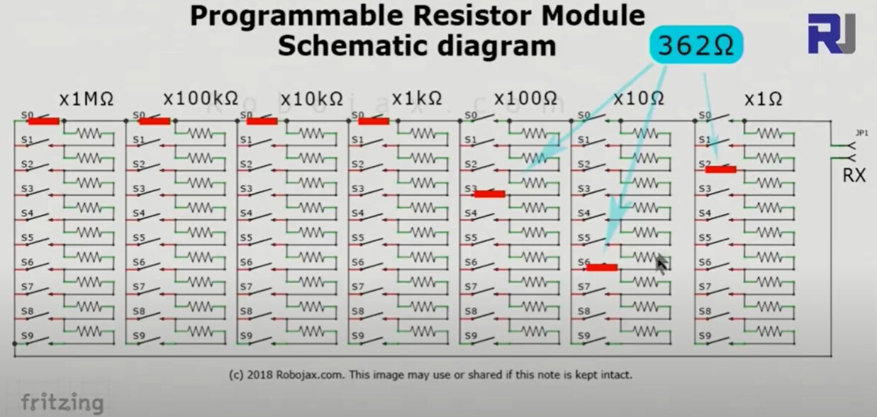
How would you replace the manual jumpers in this "Seven Decade Resistance Programmable Board" (see attachment) by "something electronic" that I could select in my arduino.
Any idea how to make this?
Thanks

This depends on what voltage and current your expecting to pass through the board. You can get programmable variable resistors but usually they cannot handle much current.
How would you replace the manual jumpers in this
The resolution of the photo isn't that great. Are those two pin slide on jumpers of the type found on PCBs
for configuring things ?
Like these?
What is your reason for wanting to replace them ? Is there something wrong with them ?
However , if you're looking for a project to kill time during the Covid lockdown it would be an excellent project to keep you busy till next year...
You could use the ADG511.
70 SWITCHES /4 (per package) ~ 18 ICs @ ~ $3.50/EA so somewhere between $65 and $100 depending on the shipping costs.
clincks:
How would you replace the manual jumpers in this "Seven Decade Resistance Programmable Board" (see attachment) by "something electronic" that I could select in my Arduino.
You really cannot. 
You could use a huge number of relays or crosspoint switches, but that would be quite ridiculously cumbersome.
raschemmel:
You could use the ADG511.
But since its switching resistance is quoted as "less than 50 Ohms", it becomes quite useless for the units, tens and hundreds of Ohms. Fail on the "seven decade" part. 
But since its switching resistance is quoted as "less than 50 Ohms", it becomes quite useless for the units, tens and hundreds of Ohms. Fail on the "seven decade" part.
Ok, you would add less than 50 ohms per switch, but if the target resistance was >200 ohms you could
subtract that from your target and adjust (change) the switch. By using a very small current source, that could be obtained by a PWM pin with an RC LPF and , you could measure the voltage drop across the resistor box (point A to Point B), and knowing
the current source value , you could calculate the ACTUAL resistance from A to B, and use a script to change
the switches until the value is close to the target, like a quasi PID loop. It would be able to zero in on the target value in a matter of seconds or less.
The current source could be disconnected after acquiring the target value by inserting a SPST relay between the current source and the decade box.
Iload =(Vb − 0.6)/Re
And of course, the resistance in the analog switch is linear, isn't it?
Would that matter if you are measuring the resistance and adjusting switches automatically ?
At the 'end of the day' the resistance obtained would be the closest possible .
Projects like this normally don't go well for the reasons mentioned. The Ron (On Resistance) of whatever you use is always going to figure into Rtotal. Even mechanical relays will have contact resistance. Really good quality decade resistance switches used very precise resistances and some very expensive switches with a silver paste on the contacts. Manufacturers like General Radio (GenRad). While I have no clue the uncertainty of your decade board it looks like the minimum resistance steps are 1.0 Ohm. The Analog Devices Precision 5 V/3 V Quad SPST Switches reflect an On resistance of about 30 Ohms and that is an "about" and that will vary.
You can look for silver or gold plated reed switches and their coils from companies like HSI and Strandex but when all is said and done you end up spending beyond your wildest dreams. Simply put it's not worth it.
Ron
Well, truth be told, as already mentioned, replacing the jumpers with anything else is probably not a practical project. Case closed.
Maybe using a single MOSFET and changing the Gate voltage could be close to get variable resistance?
So in the end, I have ordered the module to play with.
It might eventually arrive - who knows when (and if!)?
I looked at the switched resistance boxes (on eBay) - a bit too expensive for a whim - notionally about US$15 for a five decade with the lowest decade being 0.1 Ω.
Oh Larry, always have to have the last word.... 
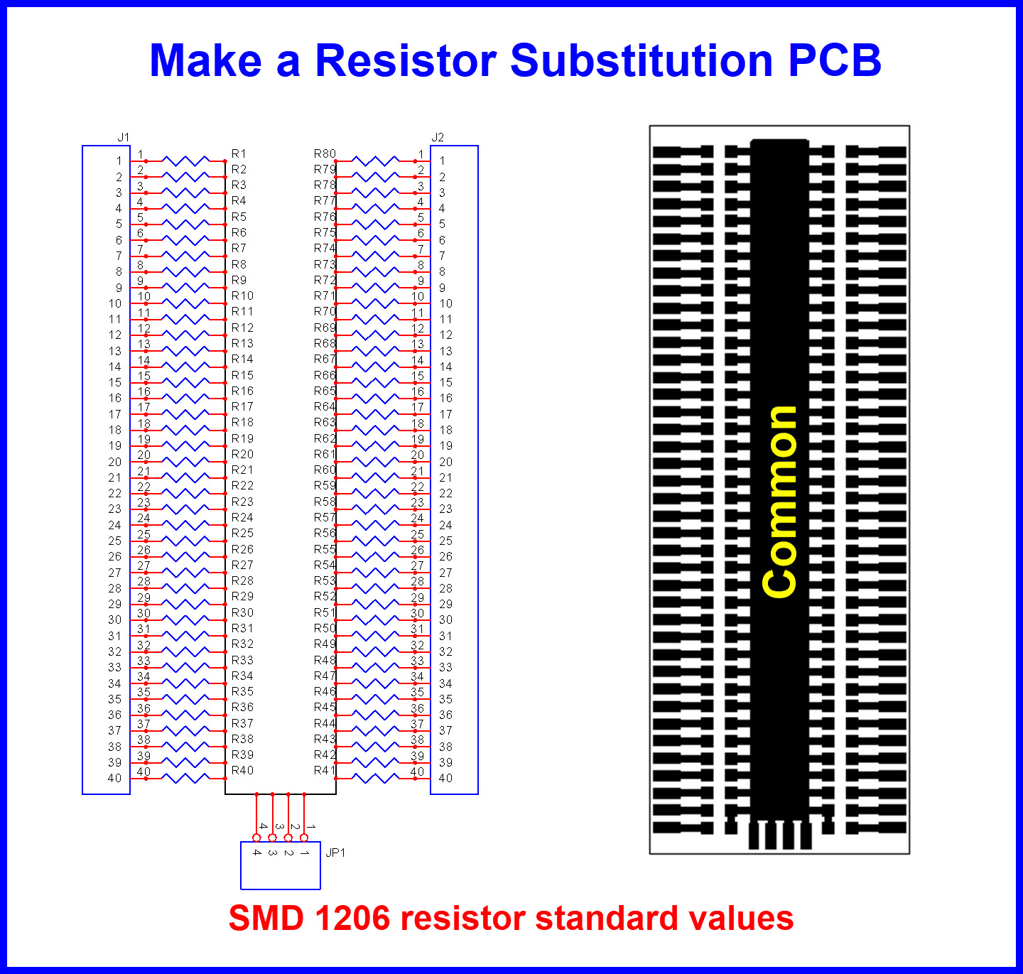
Going to have to get 80 relays to select the appropriate value.
Last word.
Who uses decade resistor boxes anymore ?
(laster word)
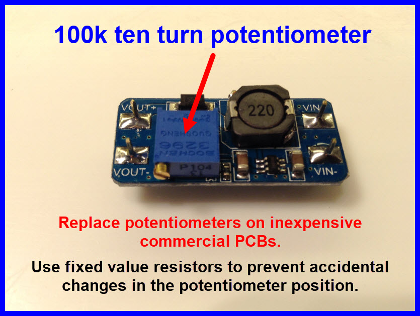
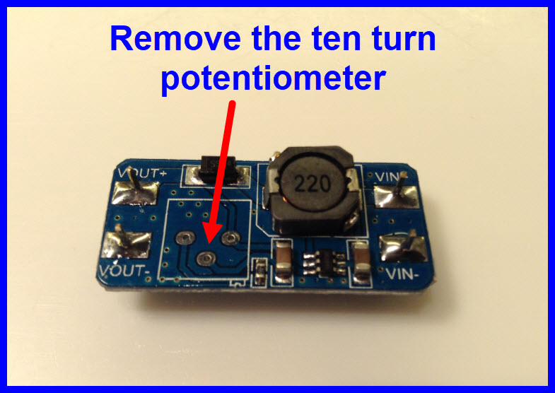
Nice ! That makes sense. I would have just removed the pot and measured the value after setting it for
12V while it was still in the board.
But this way you get standard value resistors directly.
word