I'm going to have three SMC RGB LEDs connected so that one transistor turns all three red LEDs on, one transistor turns all green ones on and one transistor turns all blue ones on.
The best connection would probably be this:
The power source will probably be 3.3 V, so the resistors will be about 75 Ohm for the red leds and 25 Ohm for the green and blue leds.
But if I want to reduce the number of resistors from 9 to 3, I could do two things. I could connect the SMC RGB LEDs in series, but that would make a voltage drop of 8.4 V on the blue and green lines. I'd need a power source of at least 9 V. And if one led blows up, the two others will go off, too.
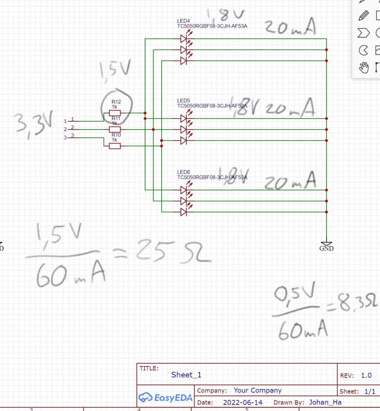
I could also connect them like this, still using only 3.3 V as the power source:
The common resistor for the red leds would be 25 Ohm and the green and blue resistors would be 8.3 Ohm. Would this work? Or will one of them blow up before the other two light up? I mean, is there a moment when each led builds up its current through, and at some point one led is on, while the other two don't yet contribute to the total current which should cause the needed voltage drop over the common resistor?
you could use transistors that receive the input signal and in their output gates you can always put a number of leds and when you choose the right type of transistor there the connections are fine but if you want to turn on a quantity that is what I tell you
You'll have to check the specs for whatever Arduino you're using. The regular (5V) Arduino is rated for 40mA "absolute maximum" from an output pin with 20mA or less "recommended". 10mA is usually enough to light an LED so 3 LEDs should be OK.
Usually each LED should have it's own resistor because you can't always count-on the current dividing equally.
Things get tricky with 3.3V... It's better if the voltage across the resistor is equal-to or greater-than the voltage across the LED. The 3.3V power supply isn't "perfect" and there is some voltage drop/loss through the chip and the more current you draw, the more the output voltage falls. The LED voltage isn't "perfect" either. The non-linear nature of an LED turns the voltage variations into exaggerated current variations. If we can drop more voltage across the resistor, which is linear, the current variations become more linear and predictable.
I'm going to have 12 spots on a big 120 * 180 cm board. Each spot has 3 SMD RGB LEDs forming a triangle. All 3 RGB LEDs will have the same colour all the time. All 12 spots might be on at the same time with all leds turned on. That's about 720 mA, so everything goes through a few ICs with 36 transistors alltogether. I still have to drive a 4*7 segment display, so there's a lot to figureout about the pins.
But this thread is only about the leds. I'm working on this PCB design:
U1 to U3 are the SMC RGB LEDs. The yellow lines mark where I add the resistors (this is the design with one resistor per each single led. I need 12 of these PCBs, so that's 108 resistors to solder (plus 36 SMC RGB LEDs and some other stuff). So I was hoping to be able to reduce the 108 resistors to 36 resistors.
On the other hand, this could be a great opportunity to invest in equipment for working with SMC stuff.
[edit]
Don't hang up on details in the PCB. The yellow line at the right edge shouldn't touch the two holes. In the very middle of the PCH is a phototransistor. The holes at the right edge from the top are: GND which is common for all components. Then we have Vcc and A0 for measuring the light that the phototransistor receives. Then we have the three lines for red, green and blue.
All up, I would recommend using a MAX7219 to drive all 36 LEDs independently, just for simplicity. This avoids using more than one resistor and you need a couple of capacitors. Obviously, you can control LEDs of one colour at the same time, it's just programming.
It will operate from 5 V (or 4.5 V if you wish to use battery power). You can drive it from 3.3 V logic, though you need to explain why .
A MAX7219 or two is definitely what I'm going for, thanks for that! But can it handle different types of leds? I got red, green and blue in the SMC RGB LEDs. And yellow in the 7 segment display.
And to have the numbers right, I have 36 SMC RGB LEDs. I don't want to treat them "independently". My first desire was to group them three and three. And one triplet I would divide into a red, a green and a blue channel. Each channel has three leds of one colour. Still ends up in 36 individual channels.
But I could have say two MAX7219 and yet divide each triplet into individual leds. That would need 108 channels to program. But as you say, it's only programming. Well, it's also a lot of wires.
The purpose of the SMC RGB LED triplet is to mark which of the 12 triplets is active. It's a floorball training device and the user is supposed to dribble the ball to the marked triplet. If I individualize each led in each SMC RGB LED in each triplet, I can create really cool effects. Not only would a triplet have a changing colour, it could also have a rotating colour pattern.
I'm not sure at this point how many actual LEDs you propose to use.
Is it 12 RGB LEDs which totals 36 actual LED chips, or is it 36 RGB LEDs totalling 108 chips?
Actually, it's not. With each MAX7219, there are never more than 16 wires going anywhere.
Now you appear to be using SMD LEDs which bring out two pins for each colour LED, not commoned. Obviously that gives you essentially complete flexibility. If they were common cathode or common anode, you would be limited to two such LEDs in each row or column of the array, so could use only 16 LEDs on each MAX7219. But it is easier to wire that way.
Strictly speaking the three colours require different voltages - which is why trying to operate them on 3.3 V is a Really Bad Idea™. Not a great problem at 5 V and the fact that the red is driven harder tends to be made up by the green and (to a lesser extent) blue appearing brighter for the same or lesser current.
36 RGB LEDs totalling 108 chips. Plus a four digit 7 segment display 8.8.:8.8.
But I read that the MAX7219 need to be very close to the leds. My leds will be spread over about 1 * 1.5 m area. And if I can avoid flickering of the leds, I go for that. The usage involves rapid eye movement and I want to avoid those annoying strobo lines on the retina.
I'm using a μC with some 80 data pins, so they don't run out, unless I really go for 108 individual leds.
Yes, I get that. Using 3.3 V in my example was a brainfart. I'm going to use 5 V.
Fair enough. In practice, what is important - as indeed with all wiring in any of these projects, is to keep all wires from one place to another, bundled as a group, precisely to avoid open loops and minimise wiring inductance (which is proportional to the spacing between wires) and EMI - which occurs as a direct consequence of wiring inductance.
Capacitive effects are minimised by keeping the wire bundle to the display, separate from other wire bundles. The strobe frequency of the MAX7219 is in the order of 600 Hz as I recall, so the frequencies involved are just a few kilohertz. With these criteria in mind, there really should be no problem in locating parts of the display half a metre or so from the MAX7219.
Connections from the microcontroller to the MAX7219 are far more of a concern regarding length.