Shaft turn counter with 2 LM393 IR modules, SSD1306 LCD and Nano

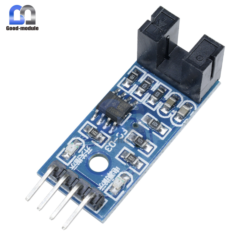
I have built up a breadboard shaft turn counter to be used as limit switches on a small high torque DC motor driving a vacuum variable capacitor. The motor rotation is controlled with an DPDT ON-OFF-ON, for reverse polariation, and a momentary switch for "fine tuning". I have manually turned and counted the number of turns from the lower to the upper stops of the VVC. In practice, I will stop turning the shaft a couple of turns above the the lower and below the upper stops to avoid damaging the VVC. The LM 393's are placed back to back, wired separately as A and B to digital pins.The shaft has a small disc configured with 4 segments the width of both A&B IRs at the cardinal points of the disc and 4 slots the same width in between. This gives 4 readings each 360 degree cycle Each time A and B are LOW a counter should advance by one for clockwise or subtracted for counter clockwise.This part isn't working. I'm using a slow 2 RPM DC motor I have on hand, because it has enough torque to turn the Russian VVC. I think I might need to eliminate multiple counts I might get due to the slow speed, or maybe, this is not a problem I'm not certain. When I change the DPDT switch, the motor reverses direction, but coding doesn't sense the counter clockwise movement. I'm probably doing something stupid and need an experienced eye to find coding mistakes. Some serial monitor printout is below. Thanks.

#include <SPI.h>
#include <Wire.h>
#include <Adafruit_GFX.h>
#include <Adafruit_SSD1306.h>

#define OLED_RESET 4
Adafruit_SSD1306 display(OLED_RESET);
#define NUMFLAKES 10
#define XPOS 0
#define YPOS 1
#define DELTAY 2

// this is the Width and Height of Display which is 128 xy 32
#define LOGO16_GLCD_HEIGHT 32
#define LOGO16_GLCD_WIDTH  128

#if (SSD1306_LCDHEIGHT != 32)
#error("Height incorrect, please fix Adafruit_SSD1306.h!");
#endif

#define moduleA 10 // Output from IR module A
#define moduleB 11 // Output from IR module B

// variables
const int runButton = 12;
int buttonState = LOW;
int modAstate;
int modBstate;
int lastAstate;
int lastBstate;
bool firstTimeFlag = false;
bool cwFlag;
bool ccwFlag;
double pulses = 0;

void setup()
{
  Serial.begin(9600);
  display.begin(SSD1306_SWITCHCAPVCC, 0x3C);  // initialize with the I2C addr 0x3C (for the 128x32)
  display.display();
  delay(2000);
  // Clear the buffer.
  display.clearDisplay();
  display.setTextColor(WHITE);
  display.drawLine(1, 37, 100, 37, WHITE);
  display.drawRect(1, 1, 126, 31, WHITE);

  display.display();
  pinMode(moduleA, INPUT);
  pinMode(moduleB, INPUT);
  pinMode(runButton, INPUT);

}
void loop()
{
  buttonState = digitalRead(runButton);
      Serial.print("buttonState = ");
      Serial.println(buttonState);
  if (buttonState == HIGH)
  {
    modAstate = digitalRead(moduleA);
          Serial.print("modAstate = ");
          Serial.println(modAstate);
    modBstate = digitalRead(moduleB);
          Serial.print("modBstate = ");
          Serial.println(modBstate);
        delay(4000);
  }
    if (firstTimeFlag == false)
    {
          Serial.print("firstTimeFlag = ");
          Serial.println(firstTimeFlag); 
      firstTimeFlag = true;    // Turn ON firstTimeFlag
          Serial.print("firstTimeFlag = ");
          Serial.println(firstTimeFlag);
      lastAstate = modAstate;  // Initialize lastAstate
      lastBstate = modBstate;  // Initialize lastBstate
    }
    whatRotation();                // Determine Rotation
    if (cwFlag == true)
    {
          Serial.print("cwFlag = ");
          Serial.println(cwFlag);
      clockWise();
    }
    else if (ccwFlag == true)
    {
          Serial.print("ccwFlag = ");
          Serial.println(ccwFlag);
      counterclockWise();
   }
  else
  {
        Serial.println("NO BUTTON ");
    delay(2000);
  }
}
void whatRotation()
{                                       // Clockwise
      Serial.println("  At whatRotation ");
  if (modAstate == HIGH && modBstate == LOW           // Read moduleA first
      || modAstate == HIGH && modBstate == HIGH
      || modAstate == LOW && modBstate == HIGH)
  {
        Serial.print("lastAstate = ");
       Serial.println(lastAstate);
        Serial.print("lastBstate = ");
        Serial.println(lastBstate);
    modAstate = digitalRead(moduleA);
        Serial.print("modAstate_1 = ");
        Serial.println(modAstate);
    modBstate = digitalRead(moduleB);
        Serial.print("modBstate_1 = ");
        Serial.println(modBstate);
    cwFlag = true;  
  }
                                     // Counter Clockwise
  else if (modBstate == HIGH && modAstate == LOW        // Polarity changed
           || modBstate == HIGH && modAstate == HIGH    // Read moduleB first
           || modBstate == LOW && modAstate == HIGH)
  {
    modBstate = digitalRead(moduleB);
        Serial.print("modBstate_1 = ");
        Serial.println(modBstate);
    modAstate = digitalRead(moduleA);
        Serial.print("modAstate_1 = ");
        Serial.println(modAstate);
    ccwFlag = true;
  }
}
void clockWise()                                       
 
{
        Serial.println("At CLOCKWISE");
  if (modAstate == LOW && modBstate == LOW)
  if( modAstate != lastAstate && modBstate != lastBstate) // Dont't add to pulses until change of state)
  {
        Serial.print("lastAstate = ");
        Serial.println(lastAstate);
        Serial.print("lastBstate = ");
        Serial.println(lastBstate);
        Serial.println("At ++.25");
    pulses += .25; // Add 1/4 turn
    display.clearDisplay();
    display.setTextSize(1);
    display.setCursor(4, 3);
    display.print("TURNS = ");
    Serial.println("TURNS ++ ");
    display.setTextSize(1);
    display.setCursor(66, 2);
    display.print(pulses);
        Serial.println(pulses);
    lastAstate = modAstate;
    lastBstate = modBstate;
    display.display();
    delay(4000);
  }
}
void counterclockWise()
{                                           // Counter Clockwise
        Serial.println("At COUNTR CLOCKWISE");
  if (modBstate == LOW && modAstate == LOW
     && modBstate != lastBstate && modAstate != lastAstate) // Dont't lower pulses until change of state
  {
        Serial.print("lastBstate = ");
        Serial.println(lastBstate);
        Serial.print("lastAstate = ");
        Serial.println(lastAstate);
        Serial.println("At --.25");
    pulses -= .25; // Subtract 1/4 turn
    display.clearDisplay();
    display.setTextSize(1);
    display.setCursor(4, 3);
    display.print("TURNS = ");
        Serial.println("TURNS -- ");
    display.setTextSize(1);
    display.setCursor(66, 2);
    display.print(pulses);
        Serial.println(pulses);
    display.display();
    lastBstate = modBstate;
    lastAstate = modAstate;
    delay(4000);
  }
}

buttonState = 0
firstTimeFlag = 0
firstTimeFlag = 1
At whatRotation
NO BUTTON
buttonState = 0
At whatRotation
NO BUTTON
buttonState = 0
At whatRotation
NO BUTTON
buttonState = 1
modAstate = 0
modBstate = 1
At whatRotation
lastAstate = 0
lastBstate = 0
modAstate_1 = 1
modBstate_1 = 1
cwFlag = 1
At CLOCKWISE
buttonState = 1
modAstate = 1
modBstate = 1
At whatRotation
lastAstate = 0
lastBstate = 0
modAstate_1 = 1
modBstate_1 = 0
cwFlag = 1
At CLOCKWISE
buttonState = 1
modAstate = 1
modBstate = 0
At whatRotation
lastAstate = 0
lastBstate = 0
modAstate_1 = 0
modBstate_1 = 1
cwFlag = 1
At CLOCKWISE
buttonState = 1
modAstate = 0
modBstate = 1

It "appears" as if you're doing a conventional quadrature encoder scheme. If so, it might be simpler to use an encoder library like that found in the IDE -> file/examples/from custom libraries.

At any rate, you have (almost) identical conditions set up for both directions - 2 if() for clockwise vs. 1 for CCW. The usual approach is when A *goes low check the state of B. If B is high then CW else CCW.

Do the IRs provide a solid logic signal for high & low?

  • Depends on your logic, encoder pins connections.

Thanks dougp for uour reply. I don't have a logic analyzer or O-scope, so I can't answer your question about the "solid logic signal". The back to back opto couplers I'm using are mounted on a small pcb with two SMD leds, one showing power, the other turns on when the IR is HIGH. Below is the link to ebay showing the ones I am using. The 4 readings for Clockwise(reading A first), the sequences are A==HIGH B==LOW, A==HIGH B==HIGH, A==LOW B==HIGH, A==LOW B==LOW. Counterclockwise(reading B first), the sequences are B==LOW A==HIGH, B==LOW A==LOW, B==HIGH A==LOW, B==HIGH A==HIGH. It is my understanding that in an if() statement the left side of the && is read first, clockwise would read A first then B and counterclockwise would read B first then A. So the coding would be similar, but with the module queries being reversed. Is this concept wrong? In looking at the example you suggested, I'm having trouble understanding them, and would like to try and correct the coding I have so far. Thanks again for you interest.

Av8ter:
It is my understanding that in an if() statement the left side of the && is read first, clockwise would read A first then B and counterclockwise would read B first then A. So the coding would be similar, but with the module queries being reversed. Is this concept wrong?

It is. These two fragments are identical.

  if (modAstate == LOW && modBstate == LOW)
  if( modAstate != lastAstate && modBstate != lastBstate) // Dont't add to pulses until change of state)
 //
 // intervening code
 //  
 if (modBstate == LOW && modAstate == LOW
     && modBstate != lastBstate && modAstate != lastAstate) // Dont't lower pulses until change of state

if( modAstate != lastAstate && modBstate != lastBstate) and its reverse,

modBstate != lastBstate && modAstate != lastAstate

is like adding 5+2 and getting 7 and then adding 2+5 and expecting a different result.

Likewise for (modAstate == LOW && modBstate == LOW) and (modBstate == LOW && modAstate == LOW). The same result is obtained in either case.

An if() statement tests for a single condition. No matter how much code or expressions are crammed between the parentheses the final result is only: Is it true or is it false?

Read more about quadrature encoders. Try your encoder with the sample sketch at the link.

Av8ter:
I don't have a logic analyzer or O-scope, so I can't answer your question about the "solid logic signal".

By this I meant whether the encoder gives a mechanical switch closure - which would require a pullup/pulldown resistor and some debouncing arrangements or, is a non-bouncing electronic signal. The link answers this.

Another concept to get under your belt is state change detection. Quite often you need, or want, to do something once when a signal *changes *as opposed to doing the something continuously as long as it's at a high or low level. See IDE -> file/examples/digital/state change detection.

Ah hah. I'm starting to get it now. I, obviously, have to dig a little deeper into the subject to fully understand, but your explanations are very helpful. Thanks for your patience.

I was a "programmer" in the 60s on 1400 series IBM and NCR Century 100 mainframe systems. I seem to have gotten dumber with each decade. Thanks again for your help.

Hi,

Thanks dougp for uour reply.
I don't have a logic analyzer or O-scope, so I can't answer your question about the "solid logic signal".
The back to back opto couplers I'm using are mounted on a small pcb with two SMD leds, one showing power, the other turns on when the IR is HIGH.
Below is the link to ebay showing the ones I am using.
The 4 readings for Clockwise(reading A first), the sequences are A==HIGH B==LOW, A==HIGH B==HIGH, A==LOW B==HIGH, A==LOW B==LOW.
Counterclockwise(reading B first), the sequences are B==LOW A==HIGH, B==LOW A==LOW, B==HIGH A==LOW, B==HIGH A==HIGH.
It is my understanding that in an if() statement the left side of the && is read first, clockwise would read A first then B and counterclockwise would read B first then A.
So the coding would be similar, but with the module queries being reversed.

Is this concept wrong?
In looking at the example you suggested, I'm having trouble understanding them, and would like to try and correct the coding I have so far.
Thanks again for you interest.

Sorry had to put some carriage returns in to see what I was reading.

Can you please post a picture of your project please so we can see how you have arranged your components?
OPs encoder units.

I think those units have indicator LEDs on them.
Your setup should be good for the slow motion action needed for tuning with variable capacitors.
Is this a remote Antenna Matching Unit?

Thanks.. Tom... :slight_smile:

It is the tuning portion of a small (3 foot diameter) Magnetic Loop antenna.

Dean

I forgot to mention that the slotted IR module pictured are the ones I'm using.

Av8ter:
I was a "programmer" in the 60s on 1400 series IBM and NCR Century 100 mainframe systems. I seem to have gotten dumber with each decade. Thanks again for your help.

The basic data handling/manipulation concepts are still there but dealing with real-time hardware requires a few adjustments.