So here's my problem. I'm actually using an Arduino nano to read an encoder (link) that has 1024 PPR. It is way too precise for what I want to do (simply get the rpm of a shaft) 0~300 RPM max. For this purpose, I decided to simply use one channel and simply count it on a rising front.
I made my lecture, so I attached channel A to an interrupt pin and the channel B too because I read on another thread that sometime, the second channel needs to be on a pull-up pin or something like that.
Also, I already succeeded to make it work with the library "Encoder.h", but it doesn't fit my needs as I need to read other sensors too and communicate via i2c and interrupts simply cut the communication. And when I used that library, from the moment you write the line myEncoder.read(), the interrupt pins will always work. I tried to use noInterrupts();, but everything stopped working.
That's why I decided to create my own code as it is relatively simple. However, using this code, I was hoping everything would work, but nothing appears in the Serial monitor. I even tried to write Serial.println("test"); inside the void loop(){} but it didn't print anything at all.
Also, another problem is that when the magnet isn't near the encoder it doesn't print anything (when I use it with the Encoder.h library) it should print 0 but instead it prints nothing.
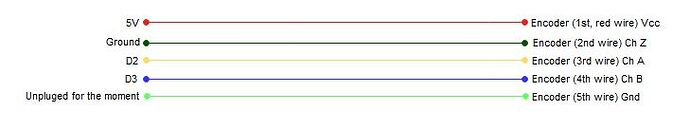
Not a good idea. Remove the B connection. Please post a wiring diagram (hand drawn preferred), showing all the connections to the encoder, with pins clearly labeled.
With TTL outputs, you usually need a pullup resistor. It may be sufficient to use pinMode(pin, INPUT_PULLUP);, but if not, use 4.7K to 5V.
I recommend using the Arduino encoder library.
To read RPM, use an encoder with MUCH reduced resolution. Interrupts will saturate the Arduino with a 1024 PPR encoder, leaving no time for anything else.
What is the pros of using it ? because I have 3 other sensors that I need to read too. If I'm using the library, I can't just shut off the interrupt pins when reading other sensors, compared to my actual code.
As @cattledog said, if I use the Z channel it is almost nothing for the arduino right?
Please, post a link to the data sheets of your product: ERCK 05TTL 1024. The link you have mentioned in post #1 takes to a brief product/sales specification page.
Thanks for the link of data sheets of the encoder.
Please, mention the sensor which you are operating uisng I2C Bus along with your encoder.
First check : Slowly turn the shaft of your encoder by one rotation and chcek that you can acquire/display ~4096 pulses for both Ch-A and Ch-B. Use both polling and interrupt methods.
Do you need to know the direction of rotation/movement?
Problem solved, I had many IDE pages opened, I closed them all and reopen only my active project and it seems to have worked
Negative.
@JCA34F thanks to you, it's a nice feature to blink the LED "L" didn't know !
Here is my updated code working
#include "Wire.h"
#define pinZ 2
#define SHT20_ADDRESS 0x40 // Define the I2C address of the SHT20 sensor

volatile uint32_t rotaryCount = 0;

// variables for encoder
const unsigned long timePeriod = 5000;
unsigned long startTime;
long startPosition;
long oldPosition = -999;

 void count(){
   rotaryCount++;
   bitWrite(PORTB,5, !bitRead(PINB,5)); // toggle LED L
 }

void setup() {
  pinMode(LED_BUILTIN,OUTPUT);
  pinMode(pinA, INPUT_PULLUP);
  attachInterrupt(digitalPinToInterrupt(pinA), count, RISING);
  Serial.begin(115200);
  Wire.begin();
}

void loop() {
  getTemp();
  readEncoder();
  delay(500);
}

void readEncoder(){
  unsigned long now = millis();
  rotaryCount = 0;
  startPosition = rotaryCount;
  while(millis() - now < timePeriod){}
  long newPosition = rotaryCount;

  float speed = (newPosition - startPosition) / (float)timePeriod * 1000 * 60;
  Serial.print("Avg speed is ");
  Serial.println(speed, 2);
  rotaryCount = 0;
}

 void getTemp(){
  Wire.beginTransmission(SHT20_ADDRESS); // Tell the sensor we want to read data
  Wire.write(0xF5); // Send the command to measure humidity
  Wire.endTransmission();

  delay(100); // Wait for the measurement to complete

  Wire.requestFrom(SHT20_ADDRESS, 3); // Request 3 bytes of data from the sensor
  while (Wire.available() < 3); // Wait for all the bytes to arrive

  uint16_t rawHumidity = Wire.read() << 8 | Wire.read(); // Combine the two bytes of data into a single 16-bit value
  Wire.read(); // Discard the checksum byte

  float humidity = -6 + 125 * (float)rawHumidity / 65536; // Convert the raw data to percent relative humidity

  Wire.beginTransmission(SHT20_ADDRESS); // Tell the sensor we want to read data
  Wire.write(0xF3); // Send the command to measure temperature
  Wire.endTransmission();

  delay(100); // Wait for the measurement to complete

  Wire.requestFrom(SHT20_ADDRESS, 3); // Request 3 bytes of data from the sensor
  while (Wire.available() < 3); // Wait for all the bytes to arrive

  uint16_t rawTemp = Wire.read() << 8 | Wire.read(); // Combine the two bytes of data into a single 16-bit value
  Wire.read(); // Discard the checksum byte

  float temperature = -46.85 + 175.72 * (float)rawTemp / 65536; // Convert the raw data to Celsius

  Serial.print("Temperature: ");
  Serial.print(temperature);
  Serial.println(" C");
  Serial.print("Humidity: ");
  Serial.print(humidity);
  Serial.println(" %RH");
}
The control will not be transferred to the next line of requestFrom() method until 3-byte data are received and stored in the I2C Serial Buffer; so, why to execute this code: while(Wire.available()<3);?
You are blocking the MCU for 5-sec -- is it good?
You are reading a 4-byte wide variable whose value might change even before the read is complete. This is a critical section which you are not protecting/guarding. Your speed measurement could be erroneous.
Honestly, this part I don't really know, took it from an example sketch and I thought it is to be more robust ?!
Yeah, I'm not sure if it's the best way to proceed, but I wait for 5 seconds and count the number of pulses that I got in 5 seconds and then I can get the average speed from a 5 seconds measure.
I'm really sure to get what you are trying to say. This part of code below is used to reset the count and then wait 5 seconds to get the number of pulses and then compute the speed from the pulses.
  unsigned long now = millis();
  rotaryCount = 0;
  startPosition = rotaryCount;
  while(millis() - now < timePeriod){}
  long newPosition = rotaryCount;