My chinese solar tracker has lasted a couple of years, it's 'detector panels' died - I replaced them with glass ones instead of the original epoxy encased ones (that delaminated) and although the voltage is the same on both types it doesn't work.
I am very capable physically making an arduino based tracker, but I have never got my head around programming of any sort.....
So I have 2 'sensor solar panels' one facing East the other West, I have relays that I can use from the chinese tracker to control the linear actuator, and I have a good soldering iron and a lot of motivation to make this work
and here is a photo of my panels on their tracker - the linear actuator is hidden by the panels in this photo
I don't know which type of arduino would be best to use - there is a 12v supply close to the panels as the linear actuator is 12v - I'm guessing an arduino uno, but I will go with whatever is recommended.
I am a pilot for a humanitarian NGO doing all our own maintenance on our planes, like I say for me fabricating, soldering etc is not a problem - it's just the programming that I struggle with
Many many thanks in advance for any help/advice offered!
You could do it that way, but how would you know which way to turn to get the maximum combined output.
The usual way is to read each sensor and compare them, the higher sensor will be at the closer angle to the sun.
You then turn your PV panels in the direction of the higher reading, until BOTH sensor values are equal.
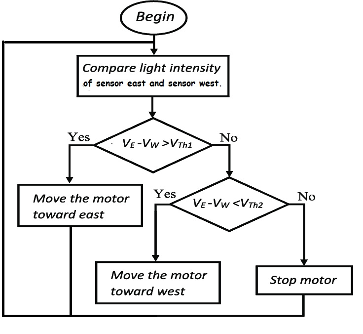
Many thanks Tom, I guess I didn't make it clear in my pdf 'plan' - the combined voltage is just for the arduino to know whether to progress to the next step or not, if the voltage is higher than the defined value then to energise the relay corresponding to the side with the higher voltage until the voltages are equal That way in low light conditions (cloudy days and night time) the panels will remain in the level position.
Being a new member (I mislaid my old login details) I couldn't put the photo inline
Many thanks for your help, and seeing the photo I realise how much I need to repaint my house
OK errr I am not sure now where the best place is to put the post . . . I don't want to put the same post in two places - and I am prepared to put in as much effort as it takes to make it work
Do you know how much of your equipment still works and what it takes to drive it? How much of it are you going to retain?
Pretty much any Arduino will work. I'd suggest getting several in case of accidents. Depending on the existing gear, you may need other external hardware to drive your actuator(s).
I guess what I was wondering was whether the controller still works and therefore whether you need something to adapt the new detector panels to work with it or whether the Arduino is the new controller. Sounds like the latter I think.
The code should be fairly simple. You'll need to figure out if the Arduino can drive the relays - sometimes the coils need more current than the Arduino can provide. Also you'll need to defend against the inductive spike when they turn off, unless that's already taken care of.
Then there's measuring the voltage. As long as the mini-panels never produce more than 5V, an Uno can read them directly.
You might consider setting up a breadboard and components to simulate your system, so you can test the code without climbing the ladder and having to wait all day.
Many thanks wildbill! If the arduino won't drive the relays that I have (that are quite small and only switching 12v at about 1-1.5 amp) I could use relays that come with and 'arduino kit' to work my relays if need be....
The mini-panels produce a maximum of around 2v each - I have never seen them even in 100% full sunlight make more than that
The breadboard idea definitely is the way to go for testing!