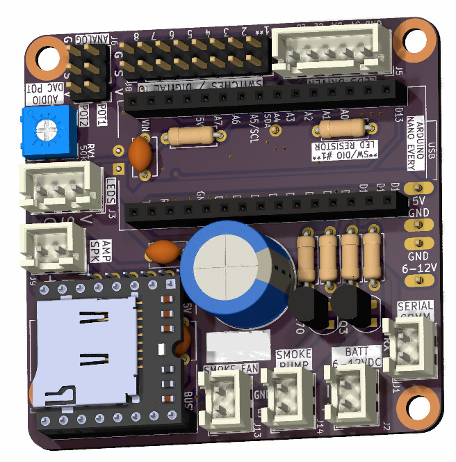
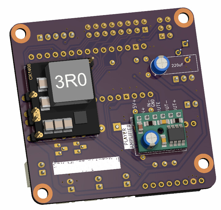
I'm working on project including a MAX7221 leds driver, an Arduino Nano Every, a DFPlayer mini and a LTK5128 5W mono amp modules.
I was wondering if putting a smalle 0.1 uF capacitor between V+ and gnd of the Arduino, the DFPlayer and the amp module is a good practice to reduce ripples, or it's overloaded. Looking at the ARduino Nano Every, it's seem that there is alreadya small capacitor on the VIN, so this one looks covered. But I can't find the schematics of the others modules...
Is it overkill and/or useless to add a small capacitor for these modules ?
The 'normal' setup is a 10uF Electrolytic, 0.1uF Ceramic, and optionally a 1 to 10 nF Ceramic. Keep them as close as possible to the power connectors or the motor connectors. Some even use two electrolytic, one goes Gnd to + and the other Gnd to -.
At worst, it won't hurt. At best, it'll save you from hunting down some switching induced spikes from, say, a power hungry MAX7221, that produce erratic behaviour in your circuit only at 2:15AM on alternate Tuesdays when Mars is ascendant.
Below is an interesting discussion of where the 0.1uF "rule" came from
I found this excerpt especially interesting:
The recommendation to use multiple values, such as 100nF + 10µF, is from the 90s and 80s when 100nF was the highest readily available ceramic capacitor with decent high frequency response. The 10µF capacitor would be an electrolytic or tantalum capacitor with poor high frequency behavior.
That has changed completely today. Now you can easily buy 10µF ceramics in 0603 or even 0402 packages. For ceramic capacitors, the high frequency response has nothing to do with the capacitor value, and everything to do with the package size of the capacitor.
With modern capacitors, it is usually pointless to connect a 100nF in parallel with a 10µF.
It's probably not going to help much. You might need a bigger capacitor.
Most datasheets recommend one or more bypass capacitors mounted near the chip. The Arduino already has them and the DFPlayer probably has them too. They are more for "stability" and high-frequency noise. A 0.1uF capacitor doesn't do much in the audio range (in this application).
It helps a LOT with negative spikes on the power supply because the capacitor can only discharge into the load. I doesn't help much more than a capacitor alone on positive spikes but it's better than a capacitor alone. There is a voltage drop across the diode so it's usually better if you have "extra voltage" with a voltage regulator following the "filter". (You'll get less drop with a Schottky diode.)
A completely separate voltage regulator provides a LOT of "filtering" too. The Arduino can use its on-board regulator with separate regulation for the audio circuitry.
I've seen a critical audio application (a preamplifier) where there were two stages of regulation... Maybe 15V regulators for most of the device, followed by 12 or 9V regulators for the more sensitive high-gain circuitry.
If you wanted to reduce power supply noise to the DFPlayer and amplifier, you'd power the DFPlayer & amp through the filter but not the Arduino or LEDs. (My drawing shows it connected to the Arduino but it's a "generic" schematic.)
That's true with a 10uF ceramic. But most 10uF capacitors are electrolytic or Tantalum and as the link says, electrolytic capacitors don't "act like" capacitors at high frequencies (high frequencies in the MHz range where you might otherwise get oscillation). For that reason, you'll often see an electrolytic and ceramic in parallel.
Yep. And I'm old school: I've always done it that way, and it works, so I see no reason to spend time "optimizing" something that's already perfectly adequate for the task.
Still, I did find it interesting to hear that the package size was the thing more so than the value of the cap.
In theory, if you're using "modules", they'll already have any "necessary" capacitors.
As others have said, adding more shouldn't hurt, and might make things "better."
I'm making a board with THT components for a prop involving sound effects, lights, smoke...
I've some noise. It does seem to come a bit from the MAX7221 (it's on another PCBs, plugged to this one with a 1x05 connector), but I can clearly ear the WS2812 adressable leds : I can ear the when the leds are blinking as exemple.
I have a trimpot on the audio signal between DFPlayer and the AMP module to top the maximum audio output. If I play with it, it does change the max volume, but also the noise : less volume more noise, more volume less noise (it seems to me).
The MAX7221 driver is powered from the Nano Every 5V, but the adressable leds are not. They are powered from the same power module as the DFPlayer and Amp module.
I've about 19 ws2812 led pixels and 10 more could be add up later, so it's too much for the 5V MCU pin to drive I think ?
Also, the space available for the PCB is small, and my board is full, I don't have space for a second power module. I don't know how to address this noise problem...
Noise in audio circuits are also a product of bad grounding. The basic rule is to use a star point ground, which means a single point at which all grounds meet.
If, for example, your audio ground shares the same conductor as your MAX7221 then variations in the current drawn by the MAX7221 will cause changes in the voltage across the conductor, which will show up as noise in the audio circuits. You have to ensure that the current for one part of the circuit does not flow in the same ground conductor as current for a different part.
I've just read few articles about star grounding, and it's really appears that is not a good idea on PCB. Star geounding was use when PCBs weren't a common thing for grounding diffrent device together. On PCBs, it would probably make thing worse. Well done solid ground planes seem to be the best solution 95% of the time.
I do have decoupling capacitors on both DFPlayer Mini and Amp module supply pins. Sure they are not SDM, but they are as close as they can get to the supply pins.
After reading a few articles on plane grounding, I think I'll try the 4 layers PCB with two inner ground layers. I will also try to have a block for audio, a block for analog, and a block for digital signals in a way that they are not crossing on other blocks.
As I said in my tutorial, this is where there is an art to what you are doing. Basically because you can't get enough information in order to produce a definitive answer.
Even changing the software running in the system affects the emissions / susceptibility of a system.