HI All
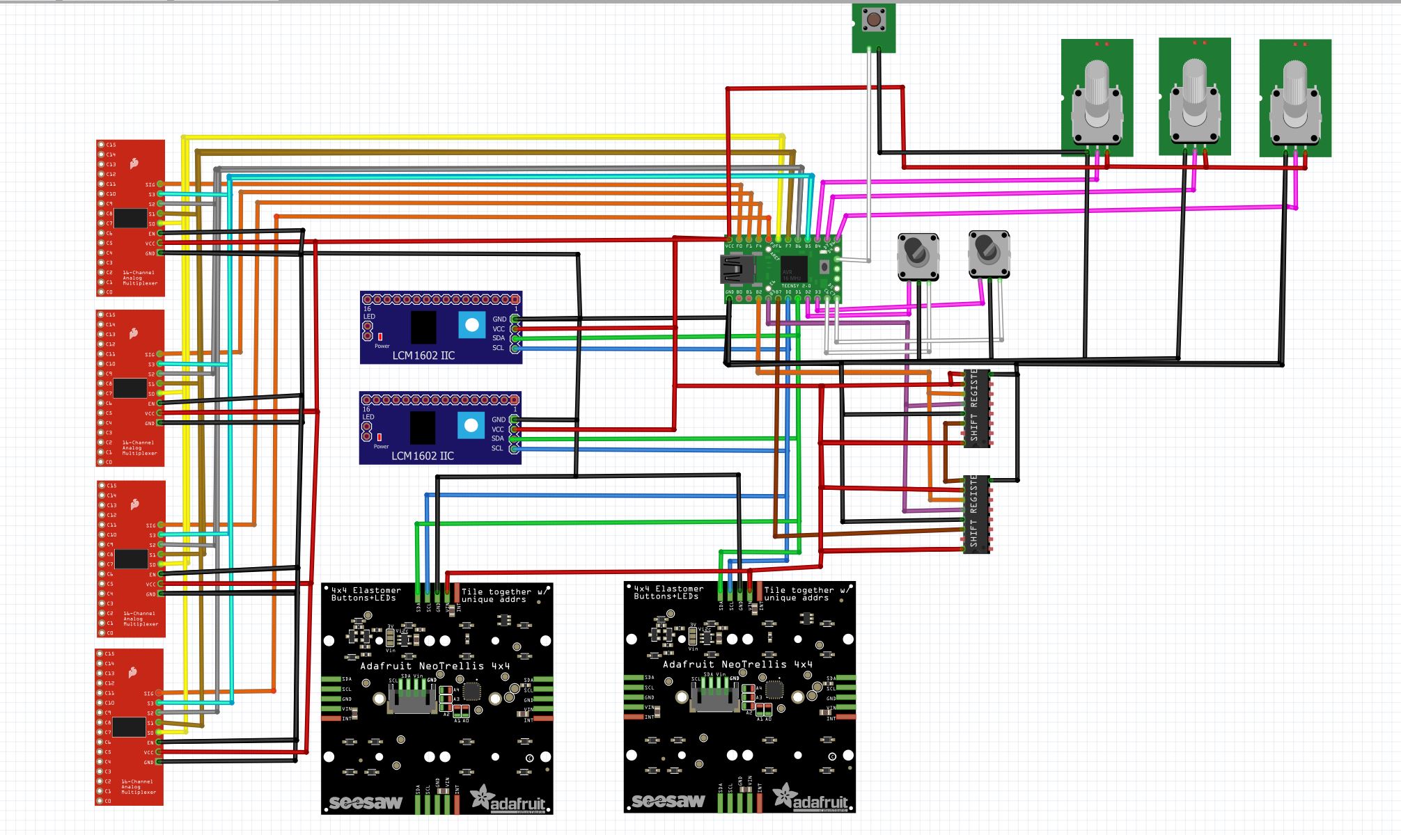
I have nearly finished to assemble my project components (midi mixer) and I woas thinking to add capacitors to smooth out the current in the circuit. Is one capacitor (lets say 500uF) added near the board supply sufficient? I am attaching the schematics of the project. It includes 4 4067 multiplexers driving 32 pots and 32 pushbuttons, 2 shift register 595 driving 16 LEDs, 2 LCD displays (I2C 16x2), 2 adafruit neotrellis I2C, then there are three additional Pots directly connected to the arduino and two encoders. The extra button on the pic is the reset button for the teensy (as you can see I have not included the pots and button attached to the multipexer and shift register in the schematics).
Also I have accidentally shortened pin 9 of the second 595 to pin 10 which is connected to Vcc. I have tested the same thing on a breadboard and it does not seem to cause problems, but what do you think (is it better to take it out again and sort it .... or it doesn't matter since that pin would be not connected to another 595)?
Maybe but usually caps are added close to the consumer.
No not at all. You also need 0.1uF ceramic capacitors to handle the high frequencies.
Perhaps reading this will help:-
Decoupling tutorial
Capacitors for voltage "so-called smoothing".
Inductors for current.
Thank you!
so to put it in simple terms the best solution would be to use one or two small capacitors (of 0.1uF to 0.01uF) and one 47uF as close as possible each multiplexer and each shift register if I understand it correctly.
like in this picture of your tutorial ![]()

is it best for the small capacitors to be the same value or a combination of 0.1uF and 0.01uF would work best (ie filtering different frequencies)?
You can try it but I am not sure if it would help because with a leaded component most of the inductance, which determines the self resonant of the part, is mainly in the leads.
A colleague of mine found that using surface mount parts found it was still effective to use 6nF parts. Once the high frequency is taken care of that is it. Adding a 0.1uF is not going to filter out any other frequencies, not covered by the smaller part.
@bluejets yes I should have said voltage not current...![]()
No both Capacitors and inductors will smooth things. It just matters exactly how you place them.
In Post#5 the 10R resistor can be replaced by an inductor for added smoothing.
That is what I said.....capacitor for voltage(parallel) and inductors for current (series) any basic power circuit shows that.
No idea what the " no" is all about.
Me thinks the usual "picky picky" responses are back on the menu.
Trust the above is more specific for your liking.
Back to "101" for you today.
guys don't argue please ![]() I am thankful to all of you for trying to help!
I am thankful to all of you for trying to help! ![]() ... peace
... peace
I have checked my multiplexer and it appear that there are two capacitors on the board already; this is the pic from the aliexpress page where I bought them :
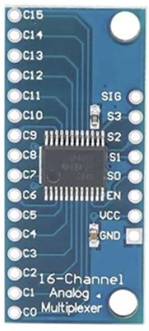
So I wander if I should just leave them as they are (just unsure whether to add or not the 47uF one).
I have been watching some stuff to understand this a bit better and wathed this video:

at the minute 13 the guy says that there is a need for a diode before the bigger capacitor, which is dealing with the low frequencies. In a circuit like mine would this be required?
Virtually all ready-made modules will have the desired buffer and decoupling capacitors on them.
If you want to add additional buffer capacitance to your project as a whole, a beefy electrolytic can indeed help. For your project, I don't see a need to go higher than 47-100uF. I'd also decouple the power input with 100nF ceramic for good measure, although you'll be hard pressed to note any difference at all in real life.
Why not a single MCP23017? Or a PCA9685 if you want to PWM the LEDs? Or simply an array of 16 addressable WS2812 LEDs that you can control through a single GPIO?
Again, with MCP23017 you can reduce the parts count.
Why not one bigger display?
Test the module in question for functionality; if it still works as intended, I'd not worry about it.
Overall I'd not worry about the capacitors too much, but have another good look at your system architecture in face of your functional requirements (which at this point only you know). I suspect you're not making optimal choices yet.
Thanks a lot for this! The reason I choose the components I have is because I have used them before and I just went back using the same thing, but I will look into the stuff you suggested.
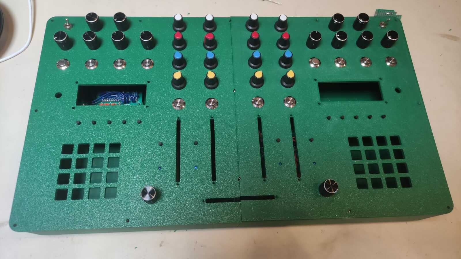
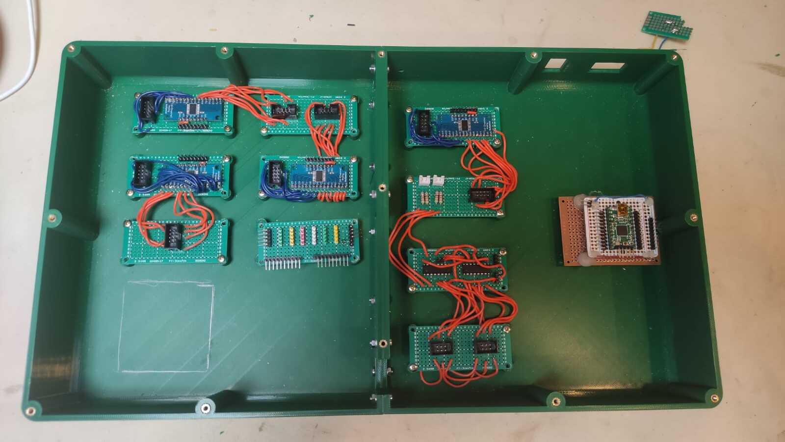
I didn't want to use LED strip as I am using LED included in the buttons see pics of my project below:
If you want to add additional buffer capacitance to your project as a whole, a beefy electrolytic can indeed help. For your project, I don't see a need to go higher than 47-100uF. I'd also decouple the power input with 100nF ceramic for good measure, although you'll be hard pressed to note any difference at all in real life.
So you mean 1 capacitor of 47-100uF for the whole project, (presumably placed across Vcc and ground of the teensy board) and 1 100nF across 5v and ground before the teensy board?
OK, I understand that argument and can get behind it. See what works best for you.
Addressable LEDs don't have to be in strips. You can buy singles as well. For your project you could even make a custom PCB.
1x 100uF electrolytic at the power input and 1x100nF ceramic across it. The 100nF acts to shunt high frequency noise to ground, while the 100uF acts as an energy buffer.
![]()
I am a bit confused (but feeling a bit thick actually)...
I thought capacitors (whether used as buffer or filters) have to be placed across positive and negative.
my power input will be the teensy board USB port so I can add the capacitor in this way (in the usb cable) :
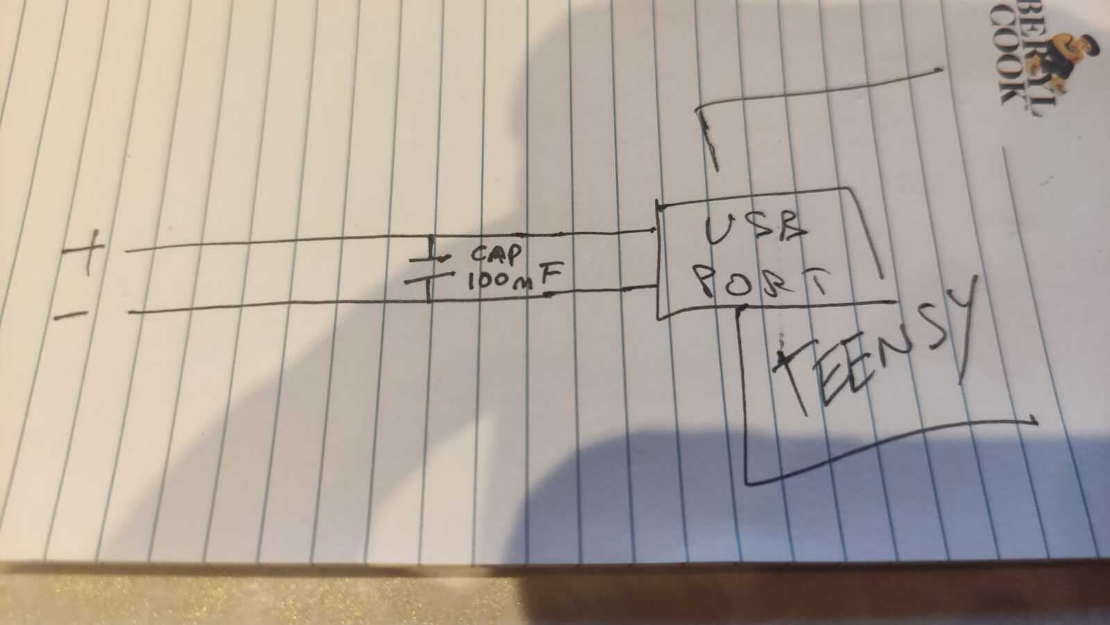
but not sure how the buffer capacitor would fit into this if not placed across + and - as the 100nF one.
or am I completely missing the point?
That's right. I did not suggest otherwise.
Place the electrolytic between Vcc and GND of your circuit, close to the USB plug that acts as your power input. The positive terminal of the capacitor goes to Vcc/5V, the negative to GND. The ceramic capacitor: same story.
These additional capacitors are not very critical/necessary in your project because the total power draw is quite limited and as said before, all your modules already have the necessary capacitors on board. If you're confused about the whole thing, just leave them out and don't worry about it.
Thank you for the clarification !! I think I misunderstood your previous post.
I think I will add them. ![]()
and thanks for you other advices about alternative components I could have used for the project!!
Good luck and have fun! I'm sure it'll work out one way or the other.
Never seen that in practice but he makes the point that this is to stop the large capacitor draining into the main power supply in the event of a short power outage. The actual need for that depends on the nature of the main power supply. In my opinion I think this is not necessary because they will be large capacitors in that main power supply that will need to be discharged, so why not discharge it into the circuit to keep it going?
But try it for yourself. Quickly turn on and off the main power supply and see if it recovers. That is if the power supply powers up or hangs. If it hangs then repeat this with a diode in place.
Hi, @fluxia
How much current will be supplied via the teensy?
Don't forget the controller is not designed as a power supply/distributor.
The PCB tracks my not be able to carry the current to your periferals.
Tom.. ![]()
![]()
![]()
![]()
in my case this would be the computer as the device I am building is a midi mixer.