I am a newbie in Arduino , So while trying to increase the number of input , 74HC165 come out as a solution
One other thing I found out that on connecting Vcc to 5v , the D1 , D2 , D3 , D4 are automatically getting high
/*
  74HC165 Shift Register Demonstration 1
  74hc165-demo.ino
  Read from 8 switches and display values on serial monitor

  DroneBot Workshop 2020
  https://dronebotworkshop.com
*/

// Define Connections to 74HC165

// PL pin 1
int load = 7;
// CE pin 15
int clockEnablePin = 4;
// Q7 pin 7
int dataIn = 5;
// CP pin 2
int clockIn = 6;

void setup()
{

  // Setup Serial Monitor
  Serial.begin(9600);

  // Setup 74HC165 connections
  pinMode(load, OUTPUT);
  pinMode(clockEnablePin, OUTPUT);
  pinMode(clockIn, OUTPUT);
  pinMode(dataIn, INPUT);
}

void loop()
{

  // Write pulse to load pin
  digitalWrite(load, LOW);
  delayMicroseconds(5);
  digitalWrite(load, HIGH);
  delayMicroseconds(5);

  // Get data from 74HC165
  digitalWrite(clockIn, HIGH);
  digitalWrite(clockEnablePin, LOW);
  byte incoming = shiftIn(dataIn, clockIn, LSBFIRST);
  digitalWrite(clockEnablePin, HIGH);

  // Print to serial monitor
  Serial.print("Pin States:\r\n");
  Serial.println(incoming, BIN);
  delay(200);
}
I placed your the code into the simulator and it appears to function.
Added: I see the output you quote did not come from the code you posted. If you post that code, maybe an error will be obvious.
shift register demo
So... I think you have a wiring error or some other not-code problem.
// https://wokwi.com/projects/369254450934472705
// https://forum.arduino.cc/t/sn74hc165n-not-working/1144268

/*
  74HC165 Shift Register Demonstration 1
  74hc165-demo.ino
  Read from 8 switches and display values on serial monitor

  DroneBot Workshop 2020
  https://dronebotworkshop.com
*/

// Define Connections to 74HC165

// PL pin 1
int load = 7;

// CE pin 15
int clockEnablePin = 4;

// Q7 pin 7
int dataIn = 5;

// CP pin 2
int clockIn = 6;


void setup()
{

  // Setup Serial Monitor
  Serial.begin(9600);

  // Setup 74HC165 connections
  pinMode(load, OUTPUT);
  pinMode(clockEnablePin, OUTPUT);
  pinMode(clockIn, OUTPUT);
  pinMode(dataIn, INPUT);
}

void loop()
{

  // Write pulse to load pin
  digitalWrite(load, LOW);
  delayMicroseconds(5);
  digitalWrite(load, HIGH);
  delayMicroseconds(5);

  // Get data from 74HC165
  digitalWrite(clockIn, HIGH);
  digitalWrite(clockEnablePin, LOW);
  byte incoming = shiftIn(dataIn, clockIn, LSBFIRST);
  digitalWrite(clockEnablePin, HIGH);

  // Print to serial monitor
  Serial.print("Pin States:\r\n");
  Serial.println(incoming, BIN);
  delay(500);
}
HTH
a7
6v6gt
July 3, 2023, 6:49pm
3
The classic error here, if that is what it is, would be solved by rotating the buttons by 90 degrees.
That code will not produce that serial monitor output, as @alto777 points out.
The 100uF should be 100nF (it is 1000x too high) and should be close to the Vcc & ground pins of the chip.
I later also tried by removing every button and just giving 5V to D1 and leaving other input as it is
Is applying a pull down resistor at every input is compulsory?
I actually didn't use any capacitor because I don't have , Could that be the problem?
Hi,
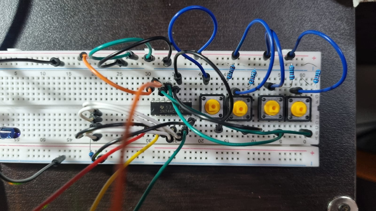
Can you please post some images of you project?
Thanks.. Tom..
PaulRB
July 4, 2023, 10:32am
8
You must apply either pull-up or pull-down resistors so that the input pins of the 74hc165 are not floating.
Yes, a 0.1uF ceramic bypass cap is required for each bare chip in a circuit. It should be connected to the Vcc and ground pins, close to the chip.
No , i don't have a DMM
In D5, d6, d7 and d8 , I used a common 10k pull down resistor as I have only 5 of them
Thanks....
Okay but isn't the function of capacitor is to smooth the DC output ? I mean is it compulsory to put it here
@sn29jan I have read your post about the same issue but didn't see any Reply marked as Solution
I also tried just by removing all the buttons and directly applying voltage individually to them. Still unable to figure it out
This is where a small inexpensive DMM would help.
Do the button pins reach and contact the protoboard sockets?
Tom..
So how can i exactly use that to find problem in this case? can you please elaborate...
Is this really what you want to do? You have effectively connected all four pins together now so setting any one of them will set all of them to the same value.
So at least these pins are now in PULL down condition , and I can check Inputs with buttons on remaining 4 inputs ...
system
January 2, 2024, 2:49am
20
This topic was automatically closed 180 days after the last reply. New replies are no longer allowed.