MarkT:
The regular NAND is 7400
Thank you! SN74HC00N is in stock ![]()
LarryD:
In fact they might be more preferable in applications.
In my "application" too? If not I'll just get the regular ones.
LarryD:
See here:
Thank you, but I'm from Germany.
MarkT:
The regular NAND is 7400
Thank you! SN74HC00N is in stock ![]()
LarryD:
In fact they might be more preferable in applications.
In my "application" too? If not I'll just get the regular ones.
LarryD:
See here:
Thank you, but I'm from Germany.
In my "application" too? If not I'll just get the regular ones.
Either will do, in a demonstration.
For 'sloping input signal' applications the hysteresis of Schmitt-trigger inputs is better.
.
LarryD:
Either will do, in a demonstration.
Great.
The datasheet of the SN74HC08 says: "±4-mA Output Drive at 5 V" - will it be enough for a LED? "Suggested using current: 16-18mA".
Most LEDs today are quite visible at 4ma.
(5V-Vled)/.004A=R
(5V-1.7Vred)/.004A=420 ohms use 430/470
.
Well I wuold prefer "really good visible" instead of "quite visible" (if possible with these ICs).
LarryD:
(5V-1.7Vred)/.004A=420
But (5-1.7)/0.004 = 825. Should I get 820 Ω?
Are carbon ones ok?
GeMir:
(5-1.7)/0.004 = 825. Should I get 820 Ω?Are carbon ones ok?
Oh my :o BAD!
820 is OK carbon or carbon film is OK.
.
The ACT logic family outputs are rated at ±20mA
dlloyd:
The ACT logic family
So I just need these and some (5-1.7)/0.02 = 165 Ω resistors?
All the 74 families have the same part numbers. 74xx02 is always quad NOR
The more obscure parts are not always available, but quad logic packages will be!
MarkT:
but quad logic packages will be!
Hm, but I can't find it here nor on the website of my local store.
Is there a SN74-NOR too in this family?
Look for CD74ACT02
I found something very similar to my demo on YouTube and the HC family with 100 Ω (?) resistors are used there.
He probably found that by using 100Ω, he could get 20mA from the output. Note that this is within Section 6.1 Absolute Maximum Ratings for continuous output current ±25mA. The Recommended Operating Conditions (section 6.3) are based on ±4mA. So you could expect reduced life expectancy operating above ±4mA and the output would fail or latch-up beyond ±25mA.
This is similar to how the specifications work with the ATmega328P in your Uno. The Absolute Maximum Ratings for continuous output current is ±40mA. The Recommended Operating Conditions are ±20mA max. So you could expect reduced life expectancy operating above ±20mA and the output would fail or latch-up beyond ±40mA.
dlloyd:
CD74ACT02
So there is no SN-version of it?
Not available at suppliers, probably obsolete, discontinued or invalid part number.
dlloyd:
probably obsolete, discontinued or invalid part number
SN stands for "Texas Instruments" for me. What does CD stands for?
Shouldn't I look for CD74ACT04, CD74ACT08 etc. (I prefer buying parts of same manufacturer)?
…
Ok, found it. CD stands for "CMOS digital logiс IC". These chips were made by Harris Semiconductor.
…
My LSs seem to work as expected without an LED connected.
void setup() {
 pinMode(9, OUTPUT);
 pinMode(10, OUTPUT);
 Serial.begin(1200);
}

int value;

void loop() {
 digitalWrite(9, LOW);
 digitalWrite(10, LOW);
 value = digitalRead(11);
 Serial.println(value);
}
…but it would be great to make an LED demo too.
Yes, it pays to understand IC part numbers.
Usually there are a few letters identifying the manufacturer, then the part number itself, then
letters/numbers that describe the particular variant (might be several packages, or different temperature
or voltage ratings, etc).
Many logic series are 74<package/variant>,
for jelly-bean logic chips no-one cares a fig about the manufacturer, so everyone just says
74HCTxx or whatever.
High temperature (mil-spec ceramic packaged) versions of 74 logic series used to have a 54 number
in place of 74, but those have died a death I think.
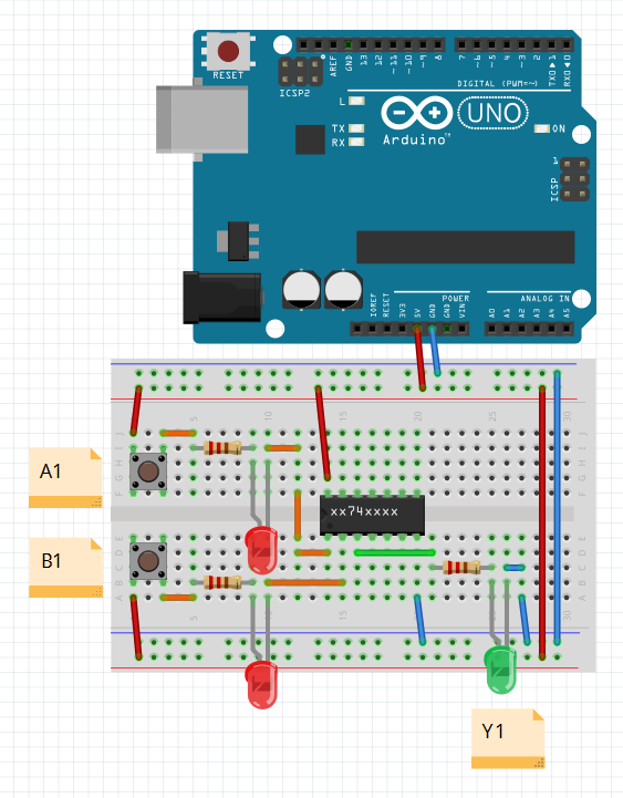
Sorry for many silly questions but for the last time here is a raw sketch of my demo circuit:
(I know, the pins are not always A1-B1-Y1, sometimes it's Y1-A1-B1 like NOR.)
Which IC-family (HC, ACT, something else) should I use in this case?
I need a NOT, AND, OR, NAND, NOR and XOR working stable.
The pinouts are the same for the same logic part across all families.
Here's how to make use of your existing LS parts using positive logic for the LED (output high = LED on, output low = LED off):
Thank you for this, but I would really prefer using ICs, resistors, buttons and wires only. So I would rather buy suitable ICs (it's really not much money).