Hi,
I am charging a supercapacitor with a solar panel. The solar panel is wired such that it can't ever exceed the voltage of the super capacitor. 3v max Voc
I found this neat smart bypass diode to use to prevent reverse current leakage when it gets dark and am using it as a blocking diode (so it's connected in series): sm74611-smart-bypass-diode
Datasheet (page 3 describes how it's 3 leads should be connected): sm74611 datasheet
Nice specs:
DC Reverse voltage 30V Maximum
Forward current 8 A Typical 15 A Maximum
Forward voltage = 26 mV ( At 8 A, T = 25°C )
Reverse leakage current = 0.3 µA (28 V Reverse Voltage, TJ = 25°C)
3.3 µA (28 V Reverse Voltage, TJ = 125°C)
The issue is based on my wiring circuit it's not charging the supercapacitor.
Any ideas?
The supercapacitor just loses it's own voltage due to leakage current.
The data sheet does not even bother to characterize the SM74611 at forward currents of less than 2A. It is certainly not designed to operate under the conditions of your test. There is quite a bit of circuitry inside that package!
A conventional silicon diode will work just fine for your very low power PV system.
Page 9 of the datasheet does say that the minimum voltage it can take is 1 volt.
The problem with a lot of diodes is the large forward voltage drop.
For the 3 volt supercapacitor I'm trying to maximize the current I get from a 3 volt panel without power loss due to forward voltage drop.
This is a continuation of another thread where I told OP to use a higher voltage solar panel, a Schottky blocking diode and an LM431-based shunt regulator on top of the supercap.
Leo..
The 150 mA limitation is still there with the LM431. With a 3V Voc, 600 mA panel I was able to charge the 10F supercapacitor in 2.5 minutes. Next set of 3V Voc solar panels I am soldering is 1.2 A.
The purpose of this thread is figuring out why the circuit of the blocking diode is not functioning the way it should when I have it wired in series.
Not with the LM431 board I linked to,
which had booster transistors with a 2A current limit IIRC.
I already expected problems with that part and minimum currents needed to use it.
Why don't you try a simple (2N5819) Schottky diode instead of the blocking diode.
The last 0.2volt of a supercap doesn't matter that much, and it will live longer when charged to below 2.7volt.
Leo..
I want to try to make full use of the specs for the smart bypass diode so I want to dedicate this thread just to the component itself and why it's not functioning the way it should.
It would be nice to charge a 3V, 450F rated supercapacitor at 8 amps, etc.... 3V, LOW-ESR, SNAP-IN ULTRACAPACITOR CELLS, (Rated Current = 287 A ???)
Or other applications where I have higher voltage solar panels and can make use of the smart bypass diode and its higher voltage and current rating etc..
If this is what you're referring to I do remember it.
Will it work for 3V super capacitors?
I'm not too well versed on the electronics details to know.
For testing purposes and safety I'm just using a 3V, 10F super capacitor for now.
I had it wired (I believe it was in parallel) based on the datasheet of the smart bypass diode and as soon as a I shaded the solar panel, the voltage on the super capacitor starts dropping significantly and way faster than the leakage current rating of the super capacitor itself. This was with no load on the super capacitor.
Why the need to fast-charge a cap that you intend to use overnight.
That supercap board I linked to is set for 2.7volt with resistors, which is a common voltage for (long-life) supercaps. It's basically a 2.7volt super-zener (low leakage below 2.7volt, and an ultra-sharp knee-point). I remember you wanted long life, because you rejected the more simple option of a LiFePo4 battery.
Still curious of how you are planning to run a 3.3volt Arduino IOT (WiFi) on a supercap.
A 3.3volt LiFePo4 battery would also be a far easier solution there.
Did you already try that Pololu boost converter overnight.
I want to use it on other projects too that have higher amperage needs.
I intend to deep sleep the devices, but not just run them over night but throughout the day.
My latest calculations say that I can charge a 3V, 450F super capacitor in 15 minutes with a 3V, 1.2A solar panel setup (voltage range from 0.55v to 2.95v charge). Spreadsheet attached for reference.
It would be on i.e. at ~300 mA consumption, over 24 hour period, 10 seconds on, ~4 minutes off of deep sleep time.
That's what I used on my project that prevent a Li-ion from blowing up during the brief moment (less than 30 seconds) between me plugging in USB power and switching to charging mode. I used a SN-240.
Which is sufficient for my needs as the battery goes from 4.2 to 3.7 while the Leonardo runs from 5.5 to 2.7. I am getting around a 0.4V drop (batt at 4.2 while measured on the mcu is 3.8) at about 80mA. However there is also a very miniscule amount of leak current, which increases as you increase the rated current of the diode (which lowers the voltage drop).
However I believe a SN-240 will be sufficient as during charging the increasingly rising cap voltage will mean that the voltage drop will be less and less (and current be less and less), until it equal to the rate the supercap self-discharges.
What are you planning to use it for?
Hold on. Let me find the previous post/thread you created.
So you want to power your nano IoT. What's the reasoning behind not using a Li-Ion battery and a regulated charger (fed with a 5-12V solar panel)?
Adafruit even have a Solar Li-ion charging thingy
And you can replace the battery with a supercap since it support 0V charging anyway
Want to power other things/projects with it too that will need more amperage.
Here were main reasons why:
Longer shelf life
perhaps the need to not replace batteries as often versus supercapacitor
faster charge times
higher amperage capabilities
Also wanted to keep it simple no complex charge circuitry just one simple bypass diode.
Today I was able to power the Nano 33 IoT with just 3V, 10F supercapacitor and it powered down ~2.5 volts (no wifi in use).
You do realize that supercap don't keep charge as well, (and that they will too fail), right?
Plus you can always use the supercap in place of a LiIon. the MCP73871 support 0V charging anyway.
How much current do you need? 5A?
Yes, a simple bypass diode is simple. But it's also somewhat difficult since there is always the (quite significant) voltage drop. And if you do have a very low voltage drop chances are you also have a high leakage current.
Yes, you can run 10x switching/zener diodes in parallel. I'm not too sure how that will result in. But it's probably not too different from a moderate Skottky
From post 1, this diode is unique because it has such a low forward voltage drop and minimal current leakage.
I don't have a specific number in terms of amperage right now but it will future proof the setup to add more peripherals to it. Right now gps and wifi are the bigger power consumers, but I plan on deep sleeping too.
DC Reverse voltage 30V Maximum
Forward current 8 A Typical 15 A Maximum
Forward voltage = 26 mV ( At 8 A, T = 25°C )
Reverse leakage current = 0.3 µA (28 V Reverse Voltage, TJ = 25°C)
3.3 µA (28 V Reverse Voltage, TJ = 125°C)
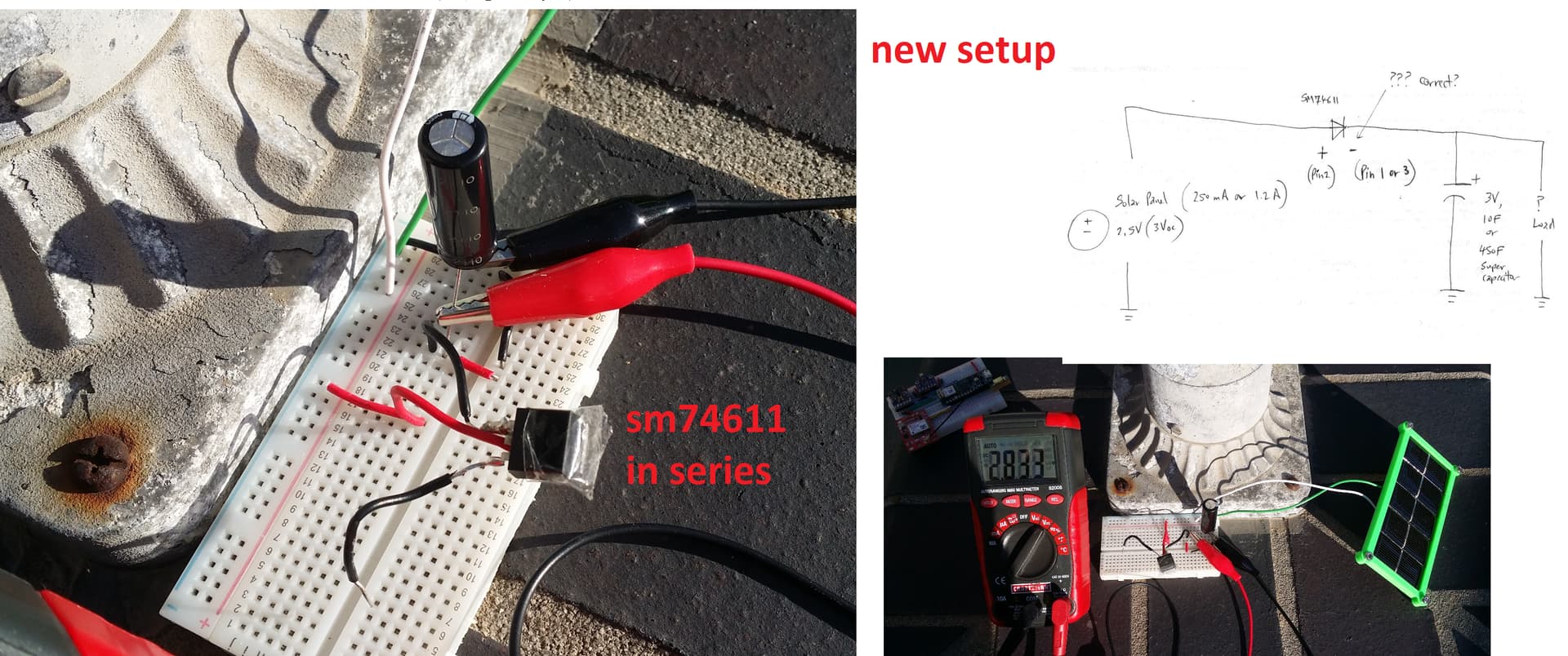
Just to give an overview of where I was before and now:
The diode was wired in parallel like a bypass diode and as soon as panel is shaded/dark, voltage dropped rapidly with no load on super capacitor.
After wiring it in series like a blocking diode, it doesn't not charge the panel at all. Current leakage of the super capacitor is all I see happening with no load connected at all.
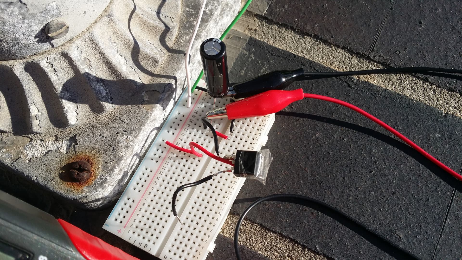
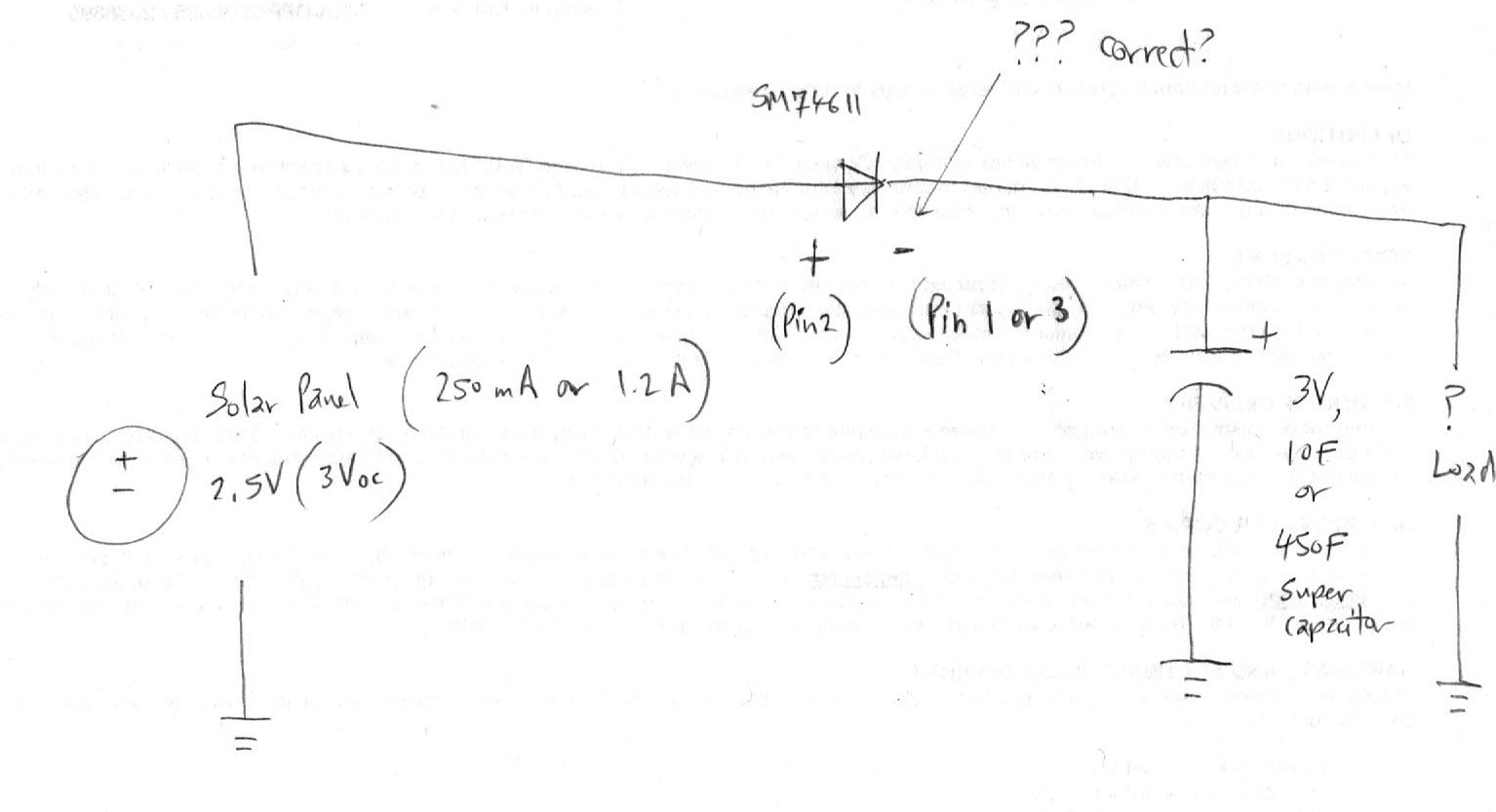
Here are schematics and pictures of the bread board setup for reference.
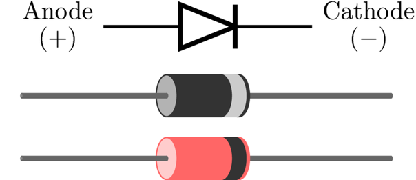
I don't know, but the Cathode is the end where the current is allowed to flow out of a diode.
And that would be pin 2 or DAP.
It also says in the datasheet that pin 1 and 3 must be connected together for proper operation.
The diode actually looks pretty cool. But it doesnt provide any data for when voltage is below 5V. The footprint is pretty hefty, though. I will probably us a LM66100 for my design.
Wow! Thanks. I thought I was messing something up with the polarity.
I just rewired with the two black leads coming from pins 1 and 3 (anode) to come from the positive terminal of the solar panel, and the red lead coming from pin 2 (cathode) goes to the positive side of the super capacitor.
It's night time here right now, but after placing my hand on the panel there is no more voltage drop on the super capacitor. Will try during day time to see if light is successful in charging it.
It BYPASSES PV cells as the light energy drops and if any PV become damaged.
It fits ACROSS each individual PV cell, NOT in series..
It will not, as you have found, do the job of BLOCKING..
A bypass diode has the job of , if in a large string of PV cells, and a couple of cells get shaded by say trees.
The bypass diode will allow the current that is generated by the uncovered PV cells to still charge the system by bypassing the current around the shaded cells.(If the potential is high enough.)
Being designed for a particular purpose does not necessarily mean it cannot be used for another case. There are slightly better alternatives (more of ideal diode controller without integrated MOSFETs), but this one should also suffice.
In the case where a row of PV cells are active, the SM74611 is "blocking" the potential "backflow" of that row into itself. And when the row of PV cells are inactive it allows a path across
You can even string multiple "solar junction box" together because when none of the panels are active the resistance from PV(-) to PV(+) is very low because of the resistors.
However, I will be slightly worried about the actual performance, since in the datasheet you can see it's not a regular diode -- it's a controller wired to a FET that decide when the FET will open (and when it will not). So from this we can say that the 74611 does not like when the voltage across is 0 and probably take significant time to switch between one and the other (both are not important as the role of a blocking diode)
The entire "ideal diode" mess is a bit of a "ehh", really. I would be trying to avoid it as best as I could. However, I am also happily conn
No. Because in my design, when you flip the power switch it disconnects the positive end of the battery from the charging IC and switch it to the rail (while disconnecting the charging IC) instead. And when connected to power my SN240 will have sufficient reverse resistance to prevent the battery from overcharging during the brief moment it take to flip the switch to connect the battery (and rail) to the charger.