I'm trying to use a microcontroller to control a P30N06LE MOSFET (on this board: https://www.amazon.com/gp/product/B00V9XF1RY/). I've taken the microcontroller out of the equation by directly hooking the control input to a constant 3.3v source. The ground is connected to the common ground and the source is hooked to either a 5v or 18v source (the solenoid is unknown but I'm fairly certain it's normally driven by 12v). The source voltage has been verified as flowing through the circuit to the output side of the MOSFET board. The ground appears to be correctly switched by the MOSFET... unless the solenoid is hooked up. If the solenoid is hooked up then the negative end of the MOSFET board reads the same source voltage (either 5v or 18v depending on what I hooked up) when measured against ground. That makes it look to me like there's a short BUT the solenoid works just fine if hooked up to a 9v battery and reads 18.2ohms across the terminals. The only other piece of the puzzle is a 1N4004 diode across the terminals where the solenoid hooks into the MOSFET board... but I've made sure half a dozen times that it is oriented correctly (stripe towards source voltage). Any ideas?
One wire from solenoid to + voltage, other wire to MOSFET drain, MOSFET source to - voltage (GND), MCU output pin to 220 Ohm resistor to MOSFET gate, MCU GND to solenoid voltage GND. Diode in parallel with sol, stripe end toward +V. 3.3V may not be high enough to drive P30N06LE to full saturation, may get warm.
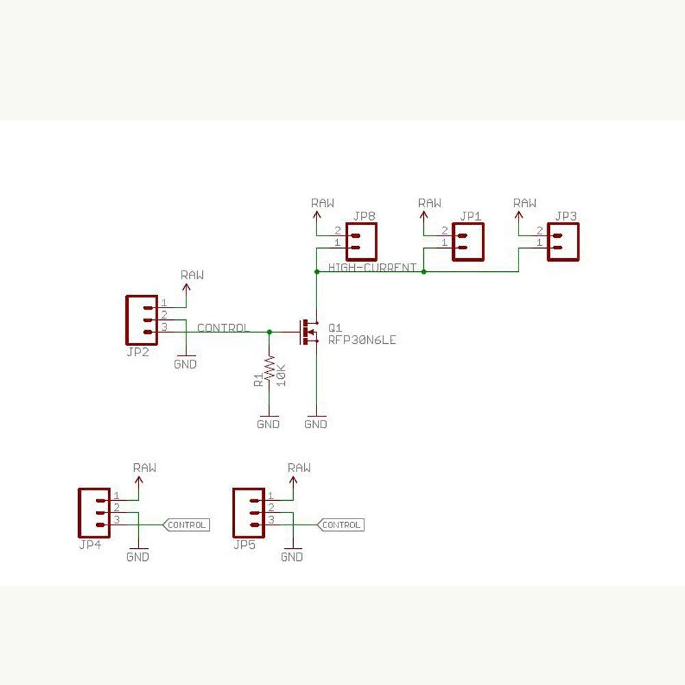
The MOSFET board comes with a 10kOhm resistor. Could a resistor with too high a value affect the action of the MOSFET? It seems to work just fine with no load hooked up to it...
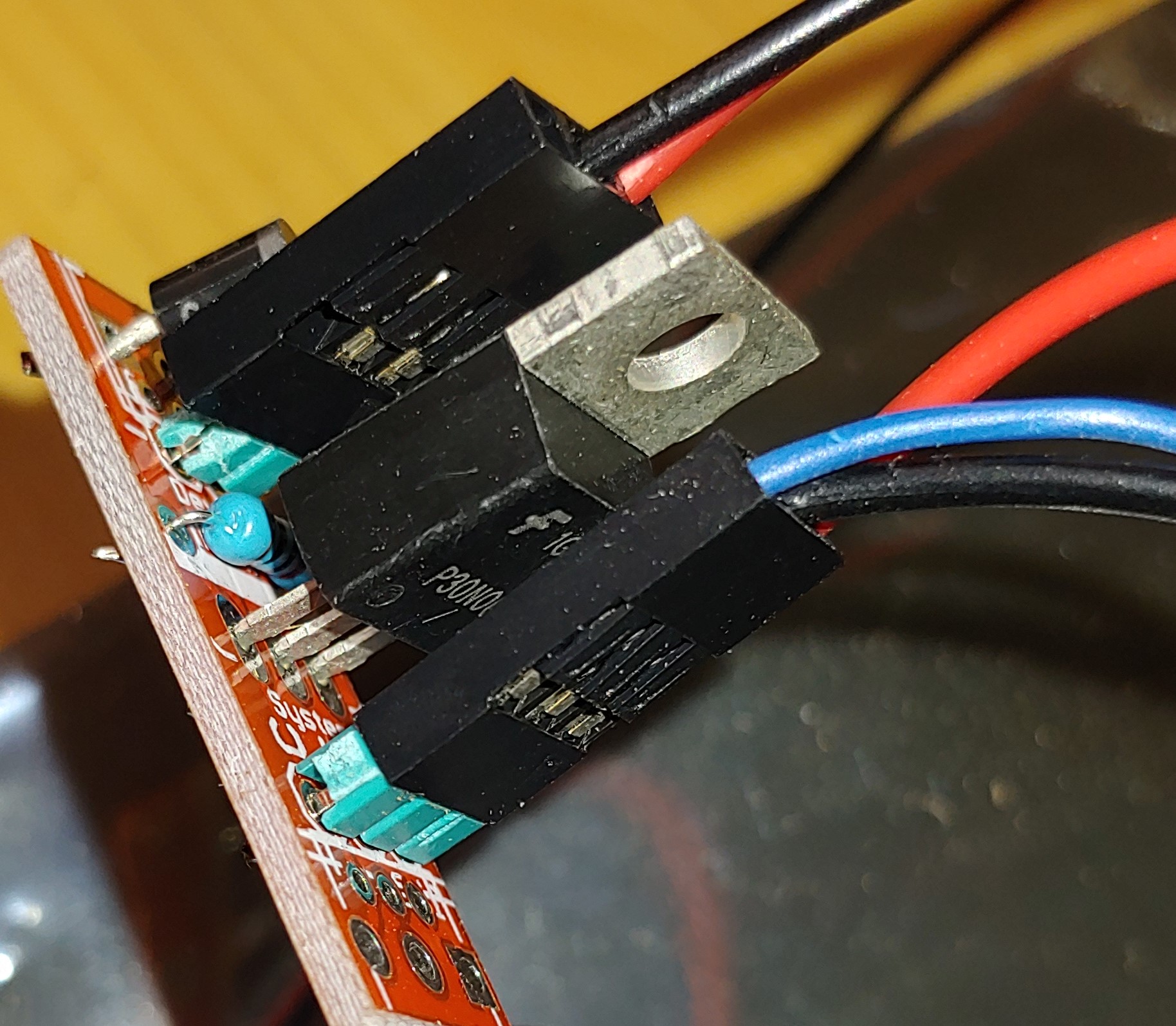
The 10k resistor keeps the gate pulled to GND (keeps the MOSFET turned OFF until a signal is applied). Do you have a connection from the solenoid power supply NEGATIVE ( - ) to your MCUs GND? What is the blue wire connected to?
In the picture attached, the left/top side are negative (black wire) and positive (red wire) out to the solenoid. The right/bottom side are control (blue wire, normally attached to a digital output pin but for troubleshooting, connected directly to 3.3v), negative (black wire), 5v or 12v positive (red wire).
As far as the "connection from the solenoid power supply NEGATIVE ( - ) to your MCUs GND" wouldn't that be going through the MOSFET when switched on? The positive (5v or 12v) is connected 100% of the time.
So if I feed it a 5v control signal then it works fine. I guess I'll have to use a small transistor to switch 5v from the 3.3v signal. Even though this part was supposed to work with 3.3v logic. Thank you for helping me troubleshoot!
MRedmon:
So if I feed it a 5v control signal then it works fine. I guess I'll have to use a small transistor to switch 5v from the 3.3v signal. Even though this part was supposed to work with 3.3v logic. Thank you for helping me troubleshoot!
The RFP30N06 is definitely not a 3V MOSFET, it requires a minimum of 5V gate drive according
to the datasheet.