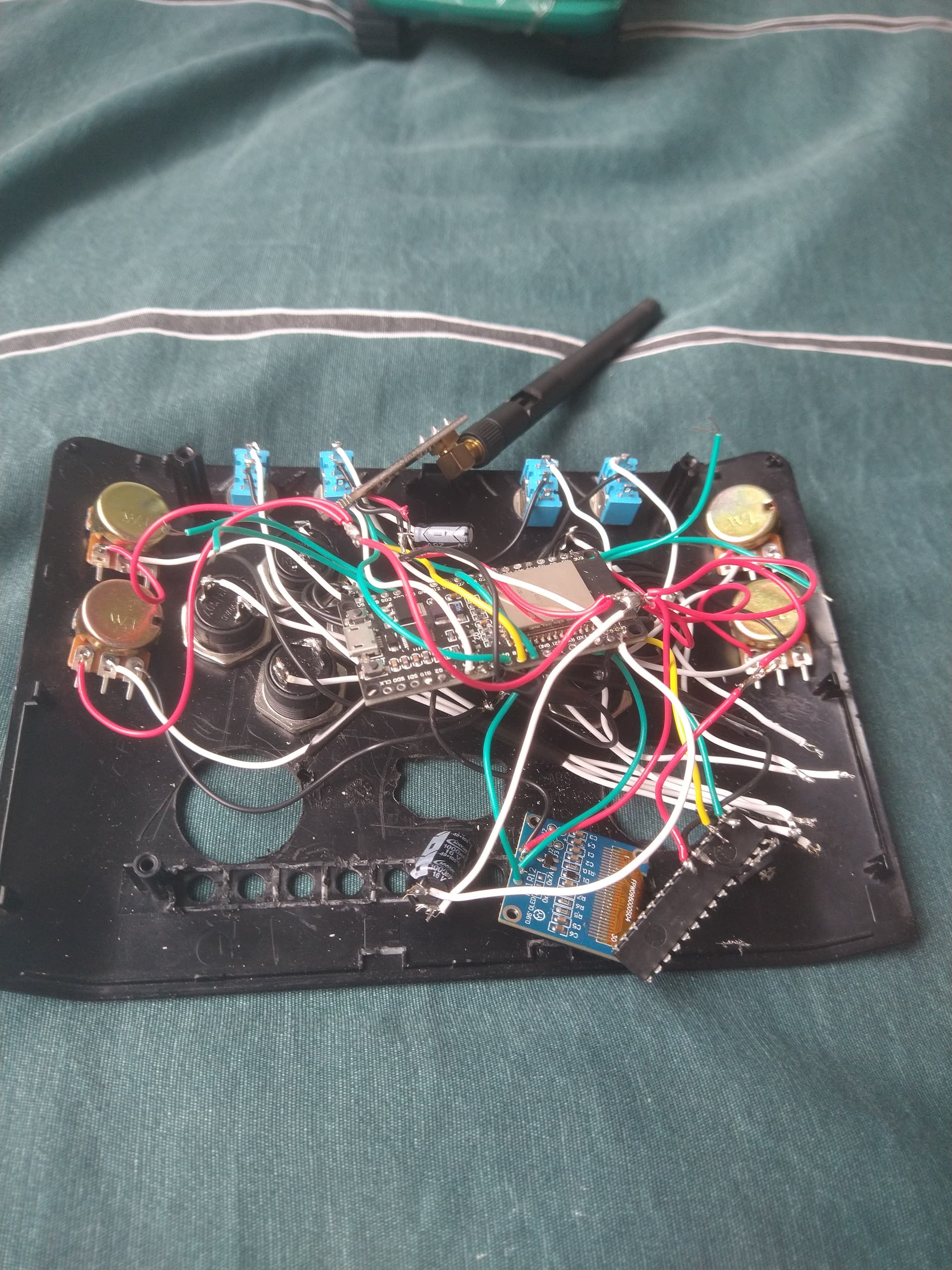
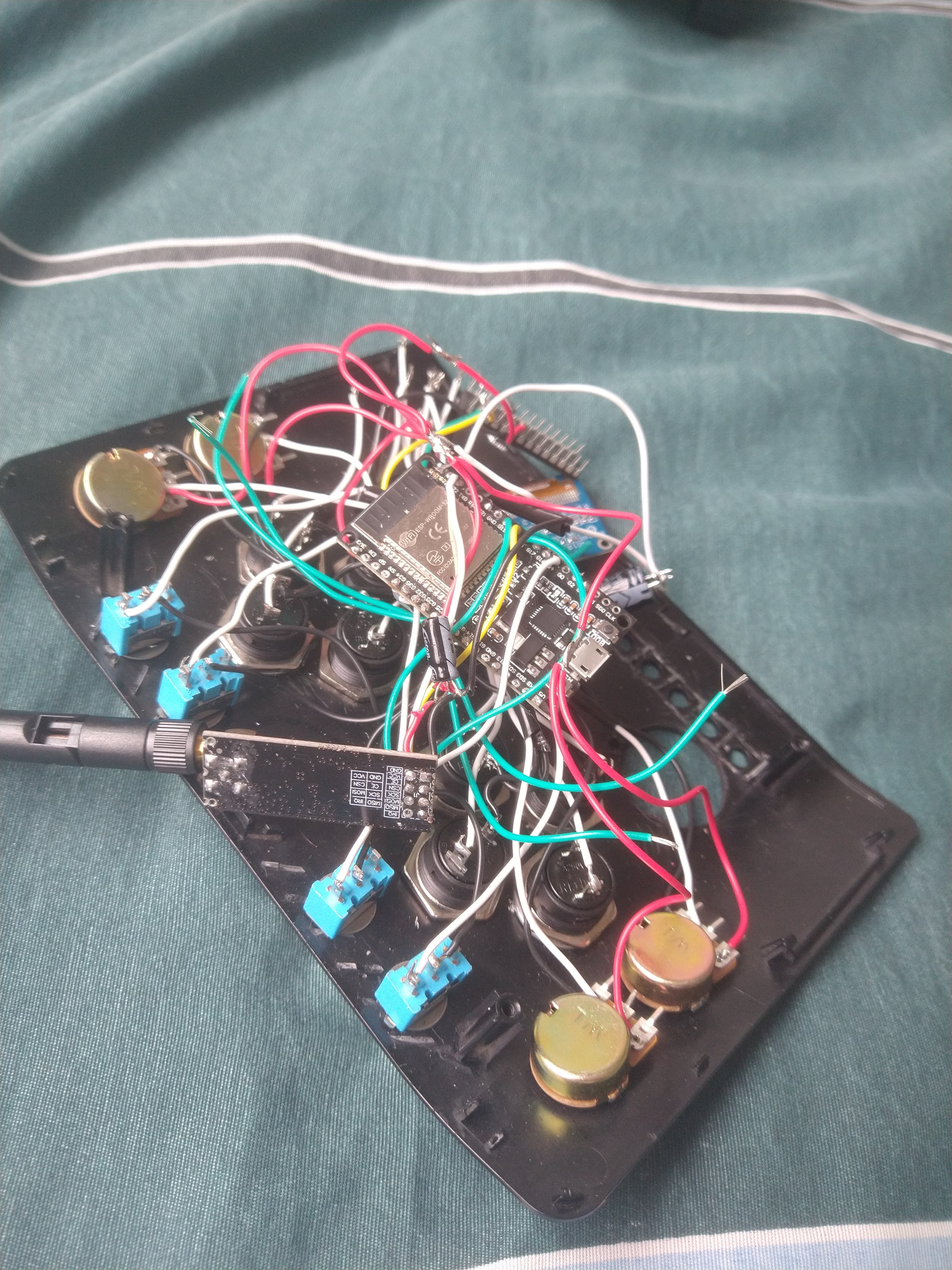
I'm making a remote control for an rc car that I'm going to make. When it was on the breadboard, the MCP23017 was working fine, but now that I've soldered all together, the code stops here:
if (!mcp.begin_I2C(0x20, &I2C_1)) { // Inicializa com o endereço 0x20
    Serial.println("Erro ao iniciar MCP23017.");
    while (1); // Pare o programa se o MCP23017 não puder ser inicializado
}
Also is there a way to print the current mcp address?
Here's the full code:
#include <Arduino.h>
#include <SPI.h>
#include <Wire.h>
#include "Adafruit_MCP23X17.h"
#include "U8g2lib.h"
#include "nRF24L01.h"
#include "RF24.h"

#define LCDWidth u8g2.getDisplayWidth()
#define ALIGN_CENTER(t) ((LCDWidth - (u8g2.getUTF8Width(t))) / 2)
#define ALIGN_RIGHT(t) (LCDWidth - u8g2.getUTF8Width(t))
#define ALIGN_LEFT 0

#define SDA1 14
#define SCL1 13

TwoWire I2C_1 = TwoWire(1);
Adafruit_MCP23X17 mcp;

U8G2_SSD1306_128X64_NONAME_F_HW_I2C u8g2(U8G2_R0);  // All Boards without Reset of the Display

// 'Max', 20x10px
const unsigned char maxbat[] PROGMEM = {
  0xfc, 0xff, 0x0f, 0x04, 0x00, 0x08, 0xf7, 0xde, 0x0b, 0xf1, 0xde, 0x0b, 0xf1, 0xde, 0x0b, 0xf1,
  0xde, 0x0b, 0xf1, 0xde, 0x0b, 0xf7, 0xde, 0x0b, 0x04, 0x00, 0x08, 0xfc, 0xff, 0x0f
};
// 'Medium', 20x10px
const unsigned char medbat[] PROGMEM = {
  0xfc, 0xff, 0x0f, 0x04, 0x00, 0x08, 0x07, 0xde, 0x0b, 0x01, 0xde, 0x0b, 0x01, 0xde, 0x0b, 0x01,
  0xde, 0x0b, 0x01, 0xde, 0x0b, 0x07, 0xde, 0x0b, 0x04, 0x00, 0x08, 0xfc, 0xff, 0x0f
};
// 'Low', 20x10px
const unsigned char lowbat[] PROGMEM = {
  0xfc, 0xff, 0x0f, 0x04, 0x00, 0x08, 0x07, 0xc0, 0x0b, 0x01, 0xc0, 0x0b, 0x01, 0xc0, 0x0b, 0x01,
  0xc0, 0x0b, 0x01, 0xc0, 0x0b, 0x07, 0xc0, 0x0b, 0x04, 0x00, 0x08, 0xfc, 0xff, 0x0f
};

// 'ConfigIcon', 13x13px
const unsigned char configIcon[] PROGMEM = {
  0x00, 0x00, 0x4e, 0x04, 0x4a, 0x04, 0x4e, 0x04, 0x44, 0x0e, 0x44, 0x0a, 0x44, 0x0e, 0x44, 0x04,
  0xe4, 0x04, 0xa4, 0x04, 0xe4, 0x04, 0x44, 0x04, 0x00, 0x00
};

// 'JogosIcon', 10x10px
const unsigned char JogosIcon[] PROGMEM = {
  0x02, 0x01, 0xfd, 0x02, 0x01, 0x02, 0xcd, 0x02, 0x45, 0x02, 0x01, 0x02, 0x79, 0x02, 0x85, 0x02,
  0x85, 0x02, 0x02, 0x01
};

// 'VoltarIcon', 10x10px
const unsigned char VoltarIcon[] PROGMEM = {
  0x30, 0x00, 0x18, 0x00, 0x0c, 0x00, 0xfe, 0x00, 0x0c, 0x01, 0x18, 0x02, 0x30, 0x02, 0x00, 0x01,
  0xfc, 0x00, 0x00, 0x00
};

// 'JoysticksIcon', 10x10px
const unsigned char JoysticksIcon[] PROGMEM = {
  0x30, 0x00, 0x78, 0x00, 0xcc, 0x00, 0xcc, 0x00, 0x78, 0x00, 0x30, 0x00, 0x30, 0x00, 0x78, 0x00,
  0xfe, 0x01, 0xff, 0x03
};

// 'PowerSavingIcon', 10x10px
const unsigned char PowerSavingIcon[] PROGMEM = {
  0x30, 0x00, 0xfc, 0x00, 0x84, 0x00, 0x94, 0x00, 0xa4, 0x00, 0x94, 0x00, 0xa4, 0x00, 0x94, 0x00,
  0x84, 0x00, 0xfc, 0x00
};

// 'ControlesIcon', 10x10px
const unsigned char ControlesIcon[] PROGMEM = {
  0x78, 0x00, 0x86, 0x01, 0x32, 0x01, 0x49, 0x02, 0x49, 0x02, 0x79, 0x02, 0x49, 0x02, 0x4a, 0x01,
  0x86, 0x01, 0x78, 0x00
};

const uint8_t *bitmaps[] = { VoltarIcon, ControlesIcon, PowerSavingIcon, JogosIcon, JoysticksIcon, VoltarIcon, VoltarIcon };
// ============================================================ //

RF24 radio(4, 5);

int MidpointEsqX = 119;
int MidpointEsqY = 119;
int MidpointDirX = 119;
int MidpointDirY = 119;
uint8_t Tolerance = 5;

uint8_t joyAX; // Joystick Esquerdo X (0-255) (Midpoint: 119)
uint8_t joyAY; // Joystick Esquerdo Y (0-255) (Midpoint: 119)
uint8_t joyBX; // Joystick Direito X (0-255) (Midpoint: 119)
uint8_t joyBY; // Joystick Direito Y (0-255) (Midpoint: 119)
uint8_t pot1;
uint8_t pot2;
uint8_t pot3;
uint8_t pot4;

struct MeuControleRemoto {
  boolean BotEsqCim = 0;
  boolean BotEsqEsq = 0;
  boolean BotEsqDir = 0;
  boolean BotEsqBai = 0;
  boolean BotDirCim = 0;
  boolean BotDirEsq = 0;
  boolean BotDirDir = 0;
  boolean BotDirBai = 0;
  boolean Mts1 = 0;
  boolean Mts2 = 0;
  boolean Mts3 = 0;
  boolean Mts4 = 0;
  byte Pot1 = 0;
  byte Pot2 = 0;
  byte Pot3 = 0;
  byte Pot4 = 0;
  byte JoyDireitaX = 127;
  byte JoyDireitaY = 127;
  byte JoyEsquerdaX = 127;
  byte JoyEsquerdaY = 127;
  byte rcBattery = 50; // 3.7v -> 5v (dividir por 10)
};

MeuControleRemoto ControleRemoto;

// Os 2 Joysticks + 4 Potenciometros
byte joyAXp = 27;
byte joyAYp = 26;
byte joyBXp = 25;
byte joyBYp = 33;
byte pot1p = 35;
byte pot2p = 34;
byte pot3p = 2;
byte pot4p = 15;

// #define joyAXp = 0;
// #define joyAYp = 0;
// #define joyBXp = 0;
// #define joyBYp = 0;

// No esp
#define Mts1Pin 16
#define Mts2Pin 17
#define Mts3Pin 32

// No MCP
#define BotEsqCimPin 0 // GPA0
#define BotEsqDirPin 1 // GPA1
#define BotEsqBaiPin 2 // GPA2
#define BotEsqEsqPin 3 // GPA3
#define BotDirCimPin 4 // GPA4
#define BotDirDirPin 5 // GPA5
#define BotDirBaiPin 6 // GPA6
#define BotDirEsqPin 7 // GPA7
#define Mts4Pin 8 // GPB0

const int numReadings = 10;  // Número de leituras para calcular a média
const int numJoysticks = 8;  // Número de entradas de joystick

// Pinos dos joysticks
const int joystickPins[numJoysticks] = {joyAXp, joyAYp, joyBXp, joyBYp, pot1p, pot2p, pot3p, pot4p};

struct Joystick {
  int pin;
  int readings[numReadings];
  int readIndex;
  long total;
  int count;
};

Joystick joysticks[numJoysticks];

int getSmoothedJoystickValue(Joystick &joystick) {
  joystick.total -= joystick.readings[joystick.readIndex];
  int newValue = analogRead(joystick.pin);
  joystick.readings[joystick.readIndex] = newValue;
  joystick.total += newValue;
  joystick.readIndex = (joystick.readIndex + 1) % numReadings;
  if (joystick.count < numReadings) {
    joystick.count++;
  }
  return joystick.total / joystick.count;
}

const unsigned char *batLevel;
const unsigned char *RCbatLevel;
char *rcName = "TESTE";
int canal = 123;
bool botaoPressionado = false;

uint8_t lastRcBattery = ControleRemoto.rcBattery;
uint8_t remoteBattery = 45;
uint8_t lastRemoteBattery = 45; // ficticia

unsigned long startMillis;  // Millis para os loops em geral
unsigned long currentMillis;  // Millis para os loops em geral
const int period = 5000;  //the value is a number of milliseconds

bool menuAtivo = false;
int selected;  // Para os menus

bool rodou = 0; // Para o display saber se ja atualizou a tela

void setup(void) {

  Serial.begin(115200);
  u8g2.begin();

  startMillis = millis();  //initial start time


  for (int i = 0; i < numJoysticks; i++) {
    joysticks[i] = {joystickPins[i], {0}, 0, 0, 0};
    pinMode(joysticks[i].pin, INPUT);
  }


  if (radio.isChipConnected())
    Serial.println("\n\nTransmitter NF24 connected to SPI");
  else Serial.println("\n\nNF24 is NOT connected to SPI");

  // Inicialize o segundo barramento I2C
  I2C_1.begin(SDA1, SCL1, 100000); // 100kHz é a frequência do I2C

  // Inicialize o MCP23017 com o barramento I2C1
  if (!mcp.begin_I2C(0x20, &I2C_1)) { // Inicializa com o endereço 0x20
    Serial.println("Erro ao iniciar MCP23017.");
    while (1); // Pare o programa se o MCP23017 não puder ser inicializado
  }

  for (int i = 0; i < 9; i++) {mcp.pinMode(i, INPUT_PULLUP);}

  // Configure o pino 0 como entrada com pull-up interno ativado
  radio.begin();                          // Inicializando o MÓDULO RF24l01 para comunicação.
  radio.setAutoAck(false);                // Desativando pacotes ACK (Pacote de Confirmação de Recebimento de Mensagem)
  radio.setChannel(100);                  // Configurando Módulo para operar no canal número 1 (você pode escolher um canal de 0 a 127) (Canal Padrão é o 76)
  radio.setDataRate(RF24_250KBPS);        // Configurando Módulo para operar em uma taxa de 250kbps (Menor taxa de dados possível para um maior alcance do rádio)
  radio.setPALevel(RF24_PA_HIGH);         // Configurando Módulo para transmitir em potência máxima
  radio.powerUp();                        // Ativando Módulo, caso entre em estado de baixo consumo.
  radio.openWritingPipe(0xE8E8F0F0E1LL);  // Abrindo o meio de comunicação entre transmissor e receptor e configurando endereço de comunicação (0xE8E8F0F0E1LL)
  radio.stopListening();                  // Interrompendo mecanismos de recepção "escuta" do Módulo
  pinMode(16, INPUT);
}

// int x = 0;

void loop()
{
  /*
  if (menuAtivo) {
    menu();
    return;
  }
  */

  joyAX = map(getSmoothedJoystickValue(joysticks[0]), 0, 4095, 0, 255);
  joyAY = map(getSmoothedJoystickValue(joysticks[1]), 0, 4095, 0, 255);
  joyBX = map(getSmoothedJoystickValue(joysticks[2]), 0, 4095, 0, 255);
  joyBY = map(getSmoothedJoystickValue(joysticks[3]), 0, 4095, 0, 255);
  pot1 =  map(getSmoothedJoystickValue(joysticks[4]), 0, 4095, 0, 255);
  pot2 =  map(getSmoothedJoystickValue(joysticks[5]), 0, 4095, 0, 255);
  pot3 =  map(getSmoothedJoystickValue(joysticks[6]), 0, 4095, 0, 255);
  pot4 =  map(getSmoothedJoystickValue(joysticks[7]), 0, 4095, 0, 255);

  if ((joyAX != ControleRemoto.JoyEsquerdaX) || (joyAY != ControleRemoto.JoyEsquerdaY) ||
      (joyBX != ControleRemoto.JoyDireitaX) || (joyBY != ControleRemoto.JoyDireitaY)) {

    if ((joyAX > (MidpointEsqX + Tolerance)) || ((joyAX < (MidpointEsqX - Tolerance)))) {
      ControleRemoto.JoyEsquerdaX = joyAX;
    }

    if ((joyAY > (MidpointEsqY + Tolerance)) || ((joyAY < (MidpointEsqY - Tolerance)))) {
      ControleRemoto.JoyEsquerdaY = joyAY;
    }

    if ((joyBX > (MidpointDirX + Tolerance)) || ((joyBX < (MidpointDirX - Tolerance)))) {
      ControleRemoto.JoyDireitaX = joyBX;
    }

    if ((joyBY > (MidpointDirY + Tolerance)) || ((joyBY < (MidpointDirY - Tolerance)))) {
      ControleRemoto.JoyDireitaY = joyBY;
    }


    /*
    Serial.print("joyAX: ");
    Serial.print(joyAX);
    Serial.print(" joyAY: ");
    Serial.print(joyAY);
    Serial.print(" | ");
    Serial.print("joyBX: ");
    Serial.print(joyBX);
    Serial.print(" joyBY: ");
    Serial.println(joyBY);
    */
  }

  ControleRemoto.Pot1 = pot1;
  ControleRemoto.Pot2 = pot2;
  ControleRemoto.Pot3 = pot3;
  ControleRemoto.Pot4 = pot4;

  ControleRemoto.BotEsqCim = mcp.digitalRead(0);
  ControleRemoto.BotEsqDir = mcp.digitalRead(1);
  ControleRemoto.BotEsqBai = mcp.digitalRead(2);
  ControleRemoto.BotEsqEsq = mcp.digitalRead(3);
  ControleRemoto.BotDirCim = mcp.digitalRead(4);
  ControleRemoto.BotDirDir = mcp.digitalRead(5);
  ControleRemoto.BotDirBai = mcp.digitalRead(6);
  ControleRemoto.BotDirEsq = mcp.digitalRead(7);

  Serial.print(ControleRemoto.Mts4);
  Serial.print(" | ");
  Serial.println(ControleRemoto.BotDirDir);

  ControleRemoto.Mts1 = digitalRead(34);
  ControleRemoto.Mts2 = digitalRead(35);
  ControleRemoto.Mts3 = digitalRead(32);
  ControleRemoto.Mts4 = mcp.digitalRead(8);


  if ((ControleRemoto.rcBattery != lastRcBattery || remoteBattery != lastRemoteBattery)/* && (rodou == 0)*/)
  {
    rodou = 1;
    Serial.println("Atualizou");
    u8g2.clearBuffer();  // clear the internal memory
    bateria();
    u8g2.setFont(u8g2_font_amstrad_cpc_extended_8u);
    u8g2.setCursor(1, 13);
    u8g2.print(F("CANAL: "));
    u8g2.setCursor(55, 13);
    u8g2.print(canal);

    u8g2.setFont(u8g2_font_t0_11_mr);
    u8g2.setCursor(ALIGN_CENTER(rcName), 30);
    u8g2.print(rcName);

    // Ícones
    u8g2.drawXBMP(107, 3, 20, 10, batLevel);
    u8g2.drawXBMP(107, 52, 20, 10, RCbatLevel);
    u8g2.drawXBMP(1, 50, 13, 13, configIcon);

    u8g2.drawHLine(0, 15, 128);
    u8g2.drawHLine(0, 47, 128);

    u8g2.sendBuffer();  // transfer internal memory to the display

    //u8g2.setPowerSave(1);
    //delay(5000);
    //u8g2.setPowerSave(0);
    //x += 1;
  }


  /*
  if (x == 5) {
    menuAtivo = true;
  }
  */

  for (int i = 0; i < 5; i++) {
    radio.write(&ControleRemoto, sizeof(ControleRemoto));
    // Serial.println(ControleRemoto.JoyDireitaX);
  }
}

void Controles() {}

void PowerSaving() {}

void Jogos() {}

void Debug() {}

// =========MENU========= //
typedef void (*FuncPtr)();

/*
void menu()
{
  const char *options[5] = {
    " Voltar",
    " Controles",
    " Power Saving",
    " Jogos",
    " Debug"
  };

  FuncPtr funcoesMenu[5] = {
    loop,
    Controles,
    PowerSaving,
    Jogos,
    Debug
  };

  const int menuLength = sizeof(options) / sizeof(options[0]);
  const unsigned long period = 20;  // Intervalo em milissegundos
  int start = 0;
  selected = 0;  // Começa no item "Voltar"

  bool last12State = HIGH; // Invertido por causa do INPUT_PULLUP
  bool last13State = HIGH;
  bool last14State = HIGH;

  while (menuAtivo) {

    if (digitalRead(14) != last14State) {

      if (digitalRead(14) == LOW) {
        last14State = LOW;
        botaoPressionado = true;

        selected += 1;

        if (selected >= menuLength) {
          selected = 0;  // Volta para o primeiro item
          start = 0;
        }

        if (selected >= start + 3) {
          start += 1;  // Ajuste o início para rolar para baixo
        }
      }
      delay(100);
    }

    last14State = digitalRead(14);

// Atualiza o estado anterior do botão

    if (digitalRead(12) == LOW) {
      botaoPressionado = true;

      if (selected == 0) {
        selected = menuLength - 1;  // Volta para o último item
        start = menuLength - 3;     // Ajuste o início para mostrar os últimos itens
      } else {
        selected -= 1;
      }

      if (selected < start) {
        start -= 1;  // Ajuste o início para rolar para cima
      }
    }

    if (digitalRead(13) == LOW) {
      botaoPressionado = true;

      if (selected == 0) {
        menuAtivo = false;
        return;
      }

      funcoesMenu[selected]();  // Chame a função correspondente ao item selecionado
    }

    if (botaoPressionado) {
      botaoPressionado = false;

      u8g2.clearBuffer();
      u8g2.setCursor(ALIGN_CENTER("MENU"), 13);
      u8g2.print(F("MENU"));
      u8g2.drawHLine(0, 15, 128);

      for (int i = start; i < start + 5 && i < menuLength; i++) {
        int yPos = 15 + (i - start) * 12;
        if (i == selected) {
          u8g2.setDrawColor(1);
          u8g2.drawBox(0, yPos + 6, 128, 10);
          u8g2.setDrawColor(0);
        } else {
          u8g2.setDrawColor(1);
        }
        u8g2.drawXBMP(0, yPos + 6, 10, 10, bitmaps[i]);
        u8g2.setCursor(14, yPos + 15);
        u8g2.print(options[i]);
      }

      u8g2.sendBuffer();
    }
  }
}

*/

void bateria()
{
  // Lê a V. bateria
  int x = 44;  // V. Ficticia (Controle)
  int y = ControleRemoto.rcBattery;  // V. Ficticia (Carrinho)

  if (x >= 50) {
    batLevel = maxbat;
  } else if (x > 43) {
    batLevel = medbat;
  } else {
    batLevel = lowbat;
  }

  if (y >= 50) {
    RCbatLevel = maxbat;
  } else if (y > 43) {
    RCbatLevel = medbat;
  } else {
    RCbatLevel = lowbat;
  }
}
And here's the diagram: