I have this Ademco Vista-15p alarm system control panel and keypad:
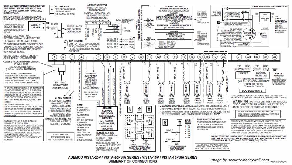
Panel's wiring diagram: http://www.home-security-systems-answers.com/images/ademco-vista-20p-007.jpg
What it looks like: http://imagehost.calabro.us/images/ademco1.JPG
I would like to "tap" into the serial communications that the board uses to talk to the keypad so I can use an arduino (jeenode) as a monitor. According to this thread the security panel uses the serial interface RS-232 4800, 8, E, 2.
In the past I've used the attached circuit to establish serial comm between raspberry pi and arduino, a logic shifter. Can I use the same circuit to interface with the security panel? Or do I need to get an RS-232 shield?
(I've already tried the proposed logic shifter circuit but didn't get anything out of it, could try to debug more but I'd like to know if I'm wasting my time with this approach)
Code snippit I'm trying to use to establish comms (from other thread posted above):
// Open serial communications:
// alarm panel uses 4800, 8, E, 2; I'll go with 4800, 8, E, 1
// because the serial port will treat the extra stop bit as an
// inter-character gap
void setup() {
  Serial.begin(4800, SERIAL_8E1);
}

void readAlarmData() {
  static int count = 0;
  static int state = 0;
  static char input_string[ALARM_STR_LEN+1] = "";

  while (Serial.available() ) {
    // get the new byte:
    char inChar = (char)Serial.read() & 0x7F;
Logic shifter uses the MPS2222A transistor
Pi and arduino both use TTL level on the pins.On Pi some of the pins are 3.3V
Since your alarm system uses RS232 it means the voltage signals are not 5V compatible, so in order for you to listen the "TX" line of the alarm system you need a RS232/TTL converter.
A good way to "see" the bytes of the communication is using a pc software like RealTerm and simply set the baud and watch what is passed on the TX wire connecting the RX pin of the RS232/TTL converter
This will give you a clear picture of the alarm system protocol
Then move to arduino programing
Ps:Looking for your picture I think the alarm uses rs485 not rs232 since rs232 is for small distances and does not allow to the wire be shared.Since the devices have addresses it should be rs485.Check it...
So it's more than just a matter of stepping the voltage down from 12+v to my 3.3 or 5v?
Regarding RS485 vs RS232, I'll look into it, I only said it was RS232 because it's mentioned by other people who have worked on the same system trying to achieve the same thing. I was just hoping my level shifter would work and I wouldn't have to order a breakout board.
How do I go about checking to see if it's RS485?
For anyone interested in the future:
The attached circuit of a level shifter worked just fine to read the security panel's data line. I did end up having to use a version of software serial because the regular serial gave me some funny results.
If anyone is trying to do the same thing simply copy SoftwareSerial2.cpp and SoftwareSerial2.h to your arduino project folder from this guy's project: GitHub - markkimsal/homesecurity: VISTA ICM replacement: Adruino firmware for Honeywell / Ademco Vista series security panels
Simple example of using it:
#define RX_PIN 6
#define TX_PIN 7

#include "SoftwareSerial2.h"
SoftwareSerial my_serial(RX_PIN, TX_PIN, true);

void process_alarm(char c) {
  //Do stuff here to process bytes from the alarm
  //Serial.print( c, HEX );

  Serial.print( c );
}

void setup() {
  Serial.begin( 9600 ); //USB connection to computer, hardware serial
  my_serial.begin( 4800 ); //Wired connection to Vista-15P, software serial 2
}

void loop() {
  while ( my_serial.available() )
    process_alarm( my_serial.read() );
}
That will get you started, now I'm trying to decode the messages, should be easier using this projects source as an example/guide.

