How would one wire this so that it works off of the JD-VCC? I can only get the relays to cycle with the jumper in place and the IN1, GND, and +5v connection to the Arduino. With +5v external, supply GND, Arduino +5v, and IN1 the LED lights but the relay doesn't engage.
I've read similar threads regarding this topic/ relay configuration but none of the explanations provided a straightforward answer.
Thank you
//the relays connect to
int IN1 = 4;
int IN2 = 5;
#define ON 0
#define OFF 1
void setup()
{
 relay_init();//initialize the relay
}
void loop() {
 relay_SetStatus(ON, OFF);//turn on RELAY_1
 delay(2000);//delay 2s
 relay_SetStatus(OFF, ON);//turn on RELAY_2
 delay(2000);//delay 2s
}
void relay_init(void)//initialize the relay
{
 //set all the relays OUTPUT
 pinMode(IN1, OUTPUT);
 pinMode(IN2, OUTPUT);
 relay_SetStatus(OFF, OFF); //turn off all the relay
}
//set the status of relays
void relay_SetStatus( unsigned char status_1, unsigned char status_2)
{
 digitalWrite(IN1, status_1);
 digitalWrite(IN2, status_2);
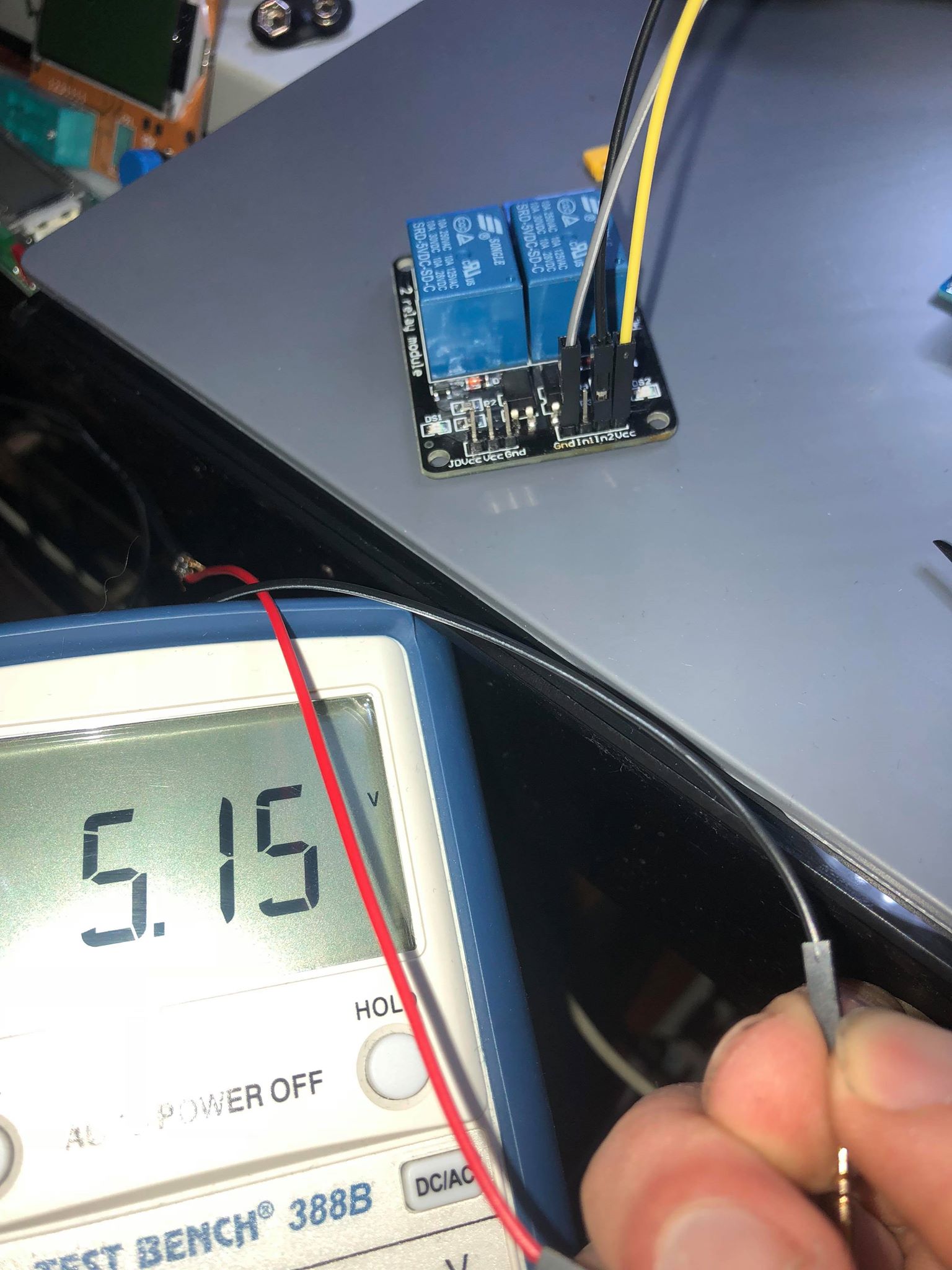
Well it's beginning to look like you might have a bad external supply, turn off all power, remove the JD-VCC jumper, remove GND wire from Arduino, connect external +5V wire (RED?) to JD-VCC pin, connect external GND (BLACK ?) to GND (-) on left terminal strip. Do you have a DMM to check voltage on JD-VCC pin?
You need to test it while connected to the module. Look at the connectors, there's a silver clip on one side, turn the connector so the clip is accessible to the meter probes.