Added to the index too.
Would you add a few eye candy images to the post too ![]() .
.
Added to the index too.
Would you add a few eye candy images to the post too ![]() .
.
Will do, give me a few minutes - busy in the shop
You didn't install THOSE bushings. They were injected molded in. I checked the Hammond web site. Show me how you install them.
Please look closely at the link in the thread, you are proven wrong ![]()
You may have bodged the econo version, but the default of that part is with inserts already installed. And your tooling time is longer than you suggest for custom work since you're using a premade case. Put it in context of doing it in an acrylic plate that needs a clean finish around the edges instead a ridge of melted plastic.
The rear plate is smooth for a reason. as it stands now, its flat & reflective. The prototypes used thru holes and nuts, simpler install yet. But it looked like crap with the nuts like steel warts on the back - yecch.
Have gone to BLACK acrylic. Clean, smooth, no lumps. Just little bits of steel peeking out of shallow black wells. No ridges.
How many products, including the case you bought, have screws into plastic? Most are self threading, but still!
. . . . . . . .
This puppy has three major unit assemblies, 1/8" acrylic front display, 1/4" acrylic rear cpu, and the wooden case. All are built separately. All are fully interchangable.
The cpu/terminal shield/PDB are a modular sub-assembly, ready for use in a variety of projects, ready to wire.
This is Low Volume Manufacturing (LVM)
The case I link did not come with inserts.
I have used a great many Hammond cases over the years, probably a few 100.
I have installed 1000s of these brass inserts, in the factory, there is a dedicated installation iron press; as a hobby, I use the method discussed throughout the link thread.
And it only takes seconds to insert these inserts as described.
I do like the black acrylic plastic sheets very much too.
This might be of interest as the panel does not need drilling, just glueing the brass nut assembly as seen in the link below.
This might be of interest too.
dont use hot glue and cardboard and don't use plastic wires i was a fool and accidentally burned them all when i was trying to solder something ![]()
Superglue, and silicone wire - see the PDF document.
How do you precisely locate the mounts? With the CNC doing the drilling, my mounts fit perfectly. How can you automatically position them without a jig? Pick & place robot? $$$ for a snall shop. $500/tool & accessories is my limit! LOL
One thing i do not like, is metal standoffs against PCB's. I use plastic standoffs and fiber washers to prevent shorts. Pet peeve.
I agree. I think I did mention that in the document; if not, I'll add it. I use nylon standoffs only. I am, after all, an electronics engineer by training... ![]()
For super glue Bob Smith accelerator is a great addition to you tool set.
Only 3-5 seconds to harden.
Also, I love Ultraviolet glue and resins are a must have too.
You add the component, PCB, etc. to the 4 feet using stand-offs; gives perfect alignment.
Add the assembly to the location on the acrylic plastic sheet.
Use a syringe to add a drop of DCM solvent, epoxy etc.
Let dry.
DCM welds the feet to the panel in 60 seconds, overnight the weld cannot be separated.
Nicely written and well thought out.
Here is something I found useful a number of years ago: http://veecad.com
Ideal for creating small circuits layouts on vero board.
I tend to use a mixture of both metal standoffs and nylon. The first for if you need a good solid point for screening or a solid earth, the second for the insulation.
Positioning is easy enough with a bit of blue tack. Mount the pillars on the PCB, position blue tack on the case then align the PCB to your satisfaction, once done, press down on the blue tack. I tend to spray the pillars with either a light oil or alcohol, which stops the pillar sticking to the blue tack.
So the part is the alignment jig. Would work well in places, but not where flush mount is used.
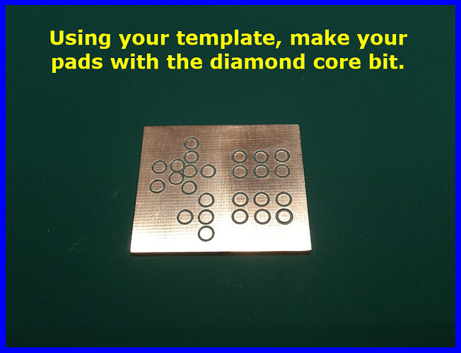
wait what diamond core bit things are actually sold??? how much do they even cost ![]()
That’s fabulous … this will spare my brain from the agony of having to so it myself. Thanks!
Look on eBay, lots of sellers, different diameters, look for super thin.
Example:
https://www.ebay.com/str/zhouzhoutools?_trksid=p2047675.m3561.l2563
I thought diamonds were super expensive. $14 is so low.