I'm not sure where this "new member" post should go, so feel free to move to a more appropriate forum, if needed.
Hello, I'm a new member!
Very soon will be receiving my first Arduinos. I purchased an UNO R3, and a Mega 2560, with bunches of bells and whistles. I'm quite excited to be starting this venture.
I'm a professional software developer for 20 years. I'm very familiar with C-based languages, so coding Arduino shouldn't be an issue. I've installed the Arduino application on my Linux system, and the interface seems pretty simple.
I also have some very basic familiarity with electronics in general. Not enough that I could build a complex device on my own, but I'm not totally green either.
I've watched the first 10 videos by Paul McWhorter on YouTube, and though I can't actually perform the projects along with the videos, I get what he's throwing so far.
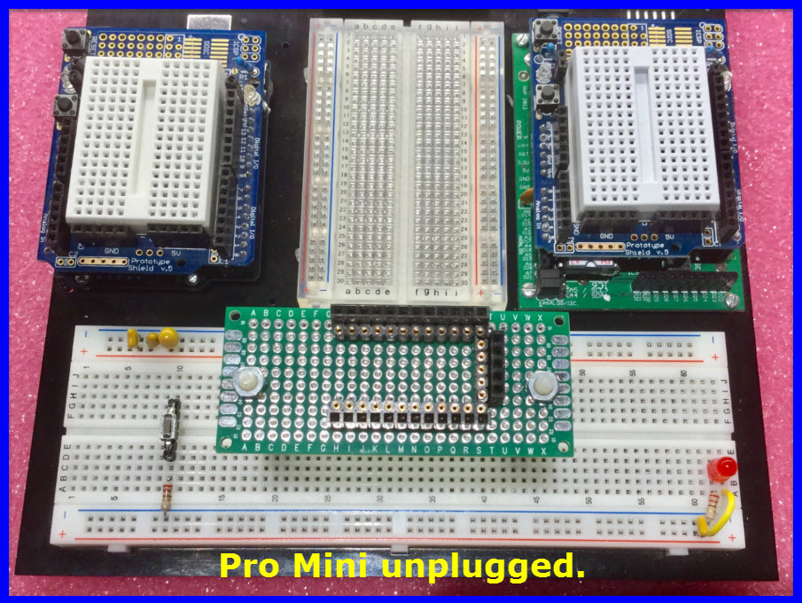
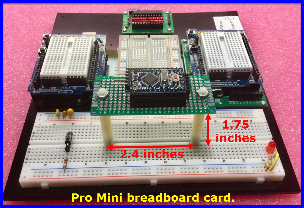
So now, on to my first question for these forums, and I imagine it should be a simple one for you guys: There doesn't seem to be a whole lot of options for mounting the UNO or Mega 2560, along with a small breadboard. I'd like a stable, but small platform that would make transport easy. The ones I've found on Amazon are for combo Arduino/Pi, with a larger breadboard, and are more bulky than I'd like. Any ideas? What solutions have you come up with?
Drop the breadboards. They quickly introduce intermittent contact when being moved.
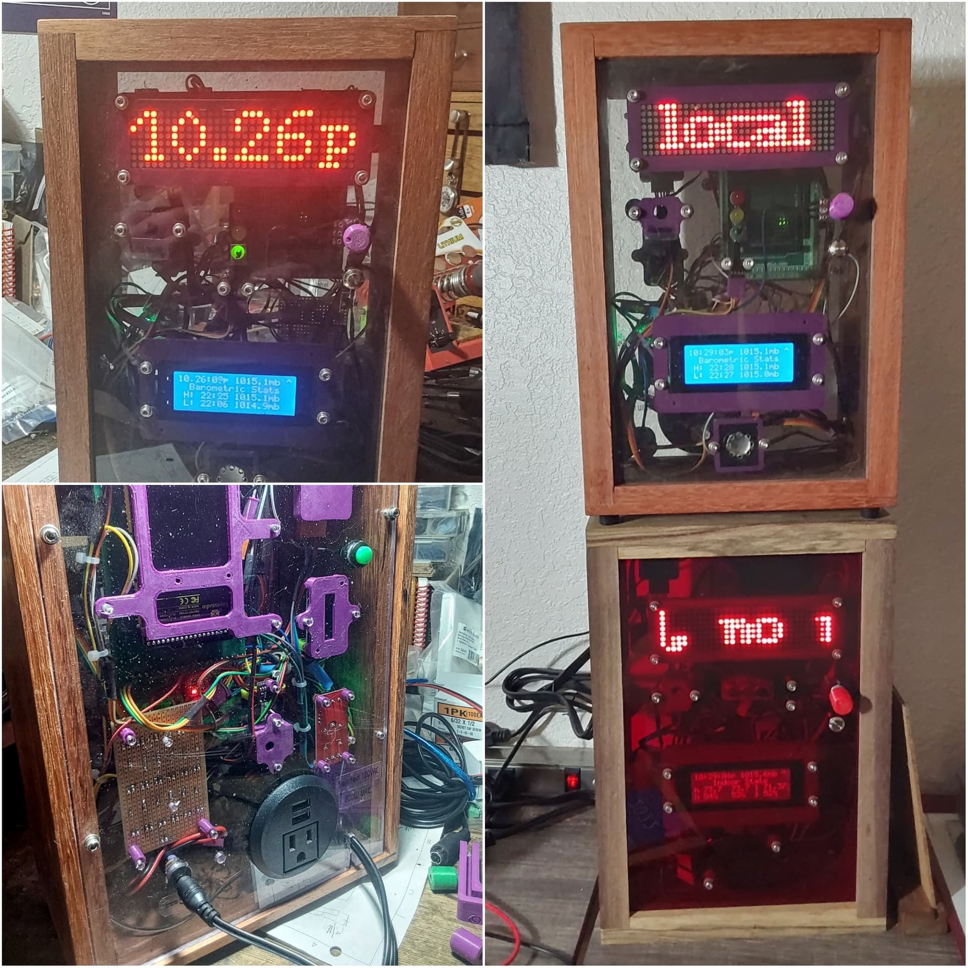
I did build a speedometer using an UNO and a NEO6-M and an I2c communicating LCD. It works like a charm. All kept in a standard plastic box with a transparent top.
And avoid the Dupont connectors once prototyping has been done, for the same reason. They look really secure when everything is sitting on the workbench.
If needed, a perf board would be a nice option. This one can be cut to shape with scissors.
I usually take a piece of plywood, paint it white then mount the hardware generally with SS #2 sheet metal screws. Works OK and stays together. Sometimes I have to add the plug board to it. I purchased a bunch of Dupont connectors and make my cables, not singles going every which place. I cheat and Purchased a bunch of them that come on a piece of ribbon cable. I remove the singles and put them together as I need.
@Railroader Why do you say drop the breadboards? I'm not building permanent circuits at this point. I just want to build a testing platform. There may eventually come a time when I want more permanent circuits.
@LarryD Wow, that looks like a fairly advanced setup! Maybe I'll be in the market for something like that at some point. Yours looks nice.
I don't mind building my own dupont cables. Is there a good, reliable source for the parts?
Options:
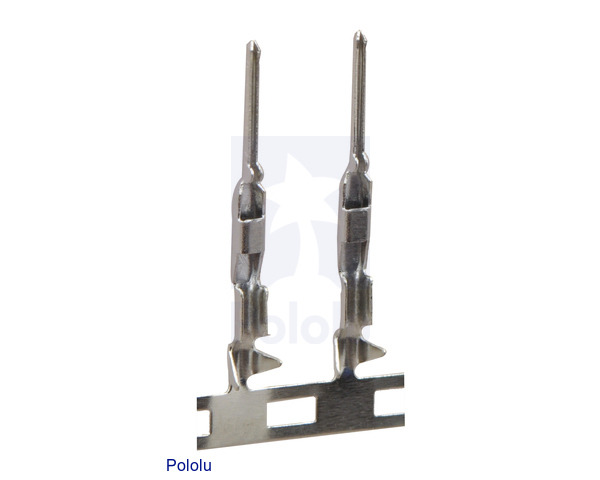
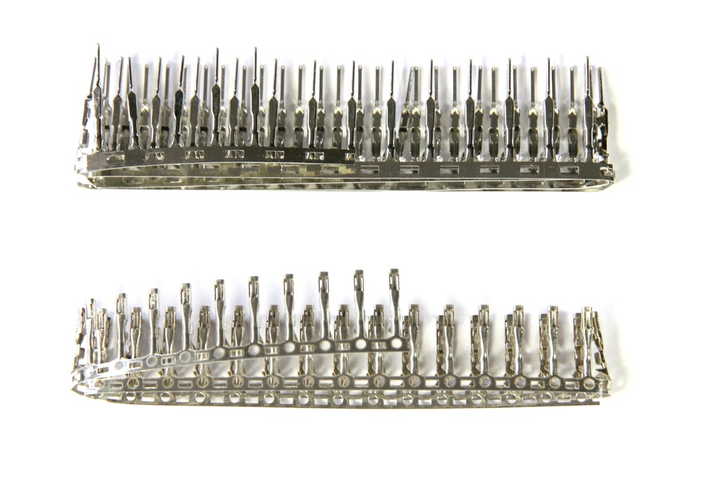
get a good crimping set to crimp power carrying wires;
similarly, crimp your own smaller, signal wires to the metal connectors and insert them into multi-way shells. Caveat: fiddly work.
Crimping done well is quite reliable.
Otherwise, if just prototyping, use the breadboard for non-power connections, and connect power wires to screw terminals if available on the device needing power. As long as the Arduino board is not the source of that power.
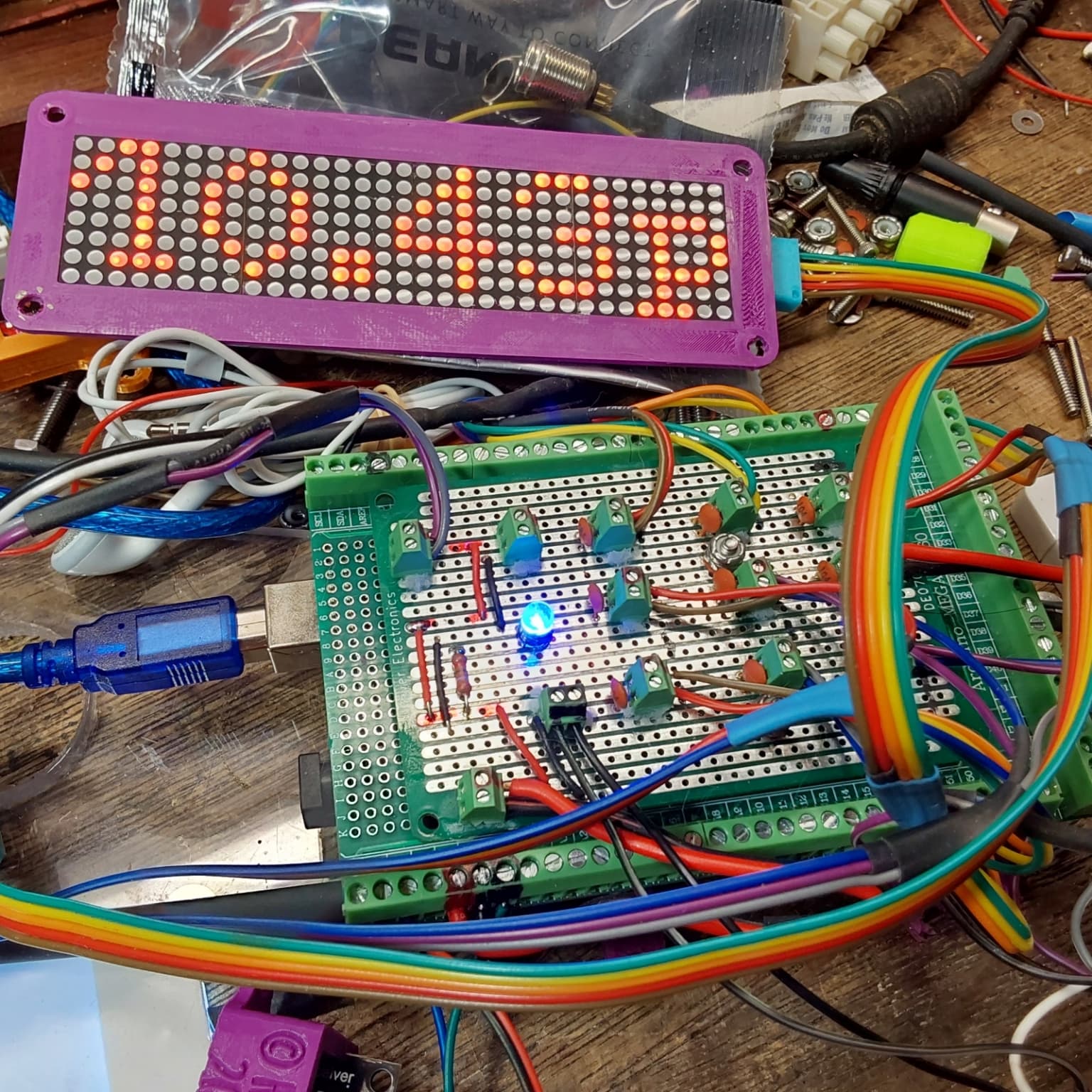
Once the PDB is made, no soldering is needed to make essentially permanent connections. The wires can be simply be stripped and twisted prior to insertion. No special tools, pins, or forms.
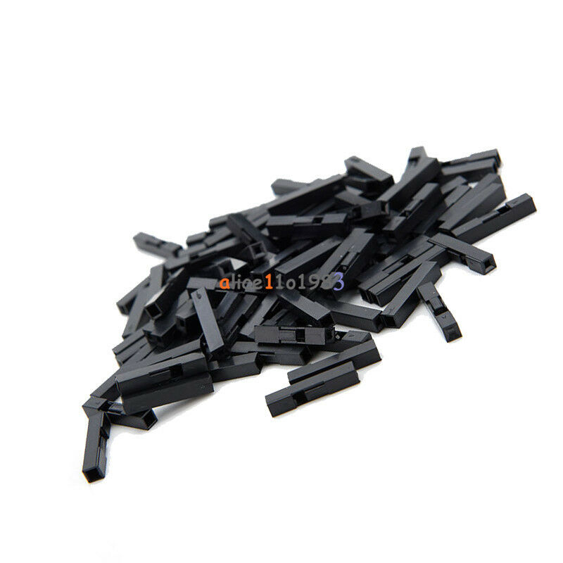
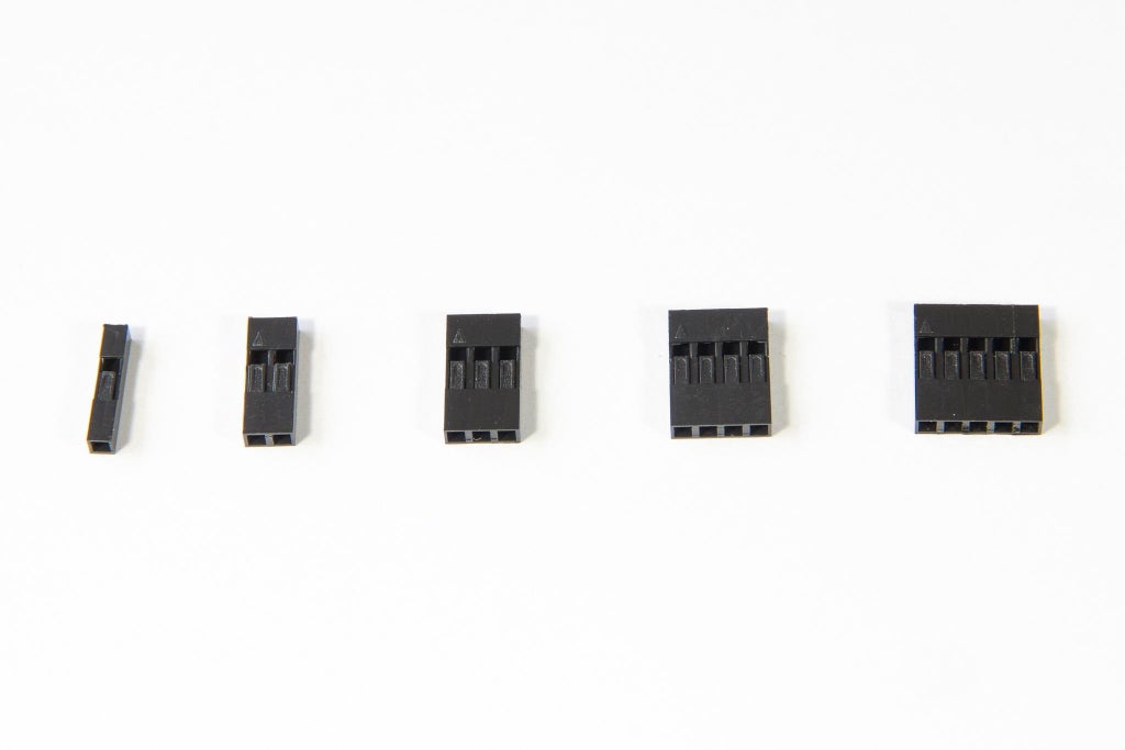
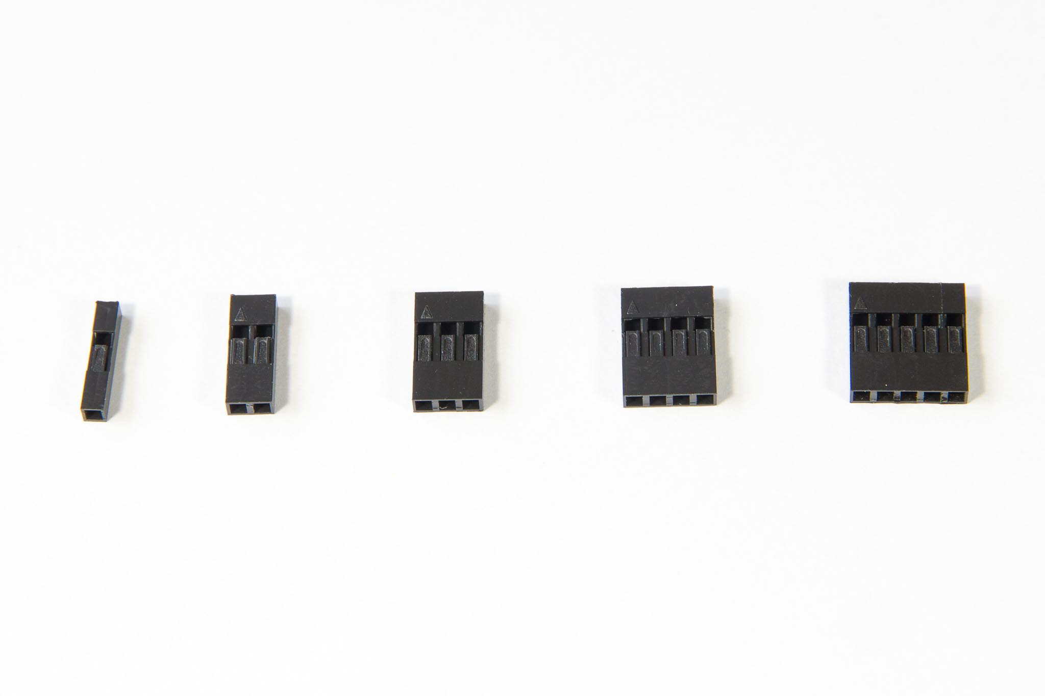
The connector shrouds group & solidify the individual DuPont pins without having to resort to crimping. The shrouds slip on or can be fed over a cut end. The far end of the cables are all DuPont F's that plug directly into whatever modules you use.
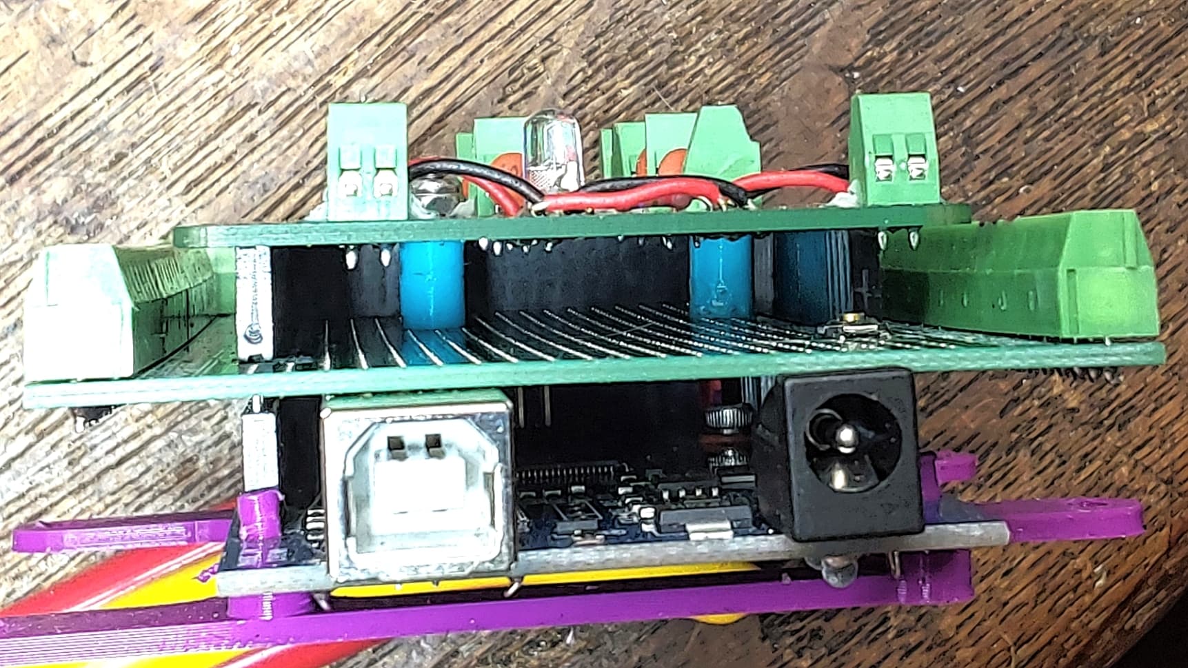
The final "sandwich" looks like this:
PDB
Terminal Shield
Mega
3D printed mounting base (wide to clear edges of terminal shield)
The entire unit panel mounts as an assembly with four #6 screw holes.
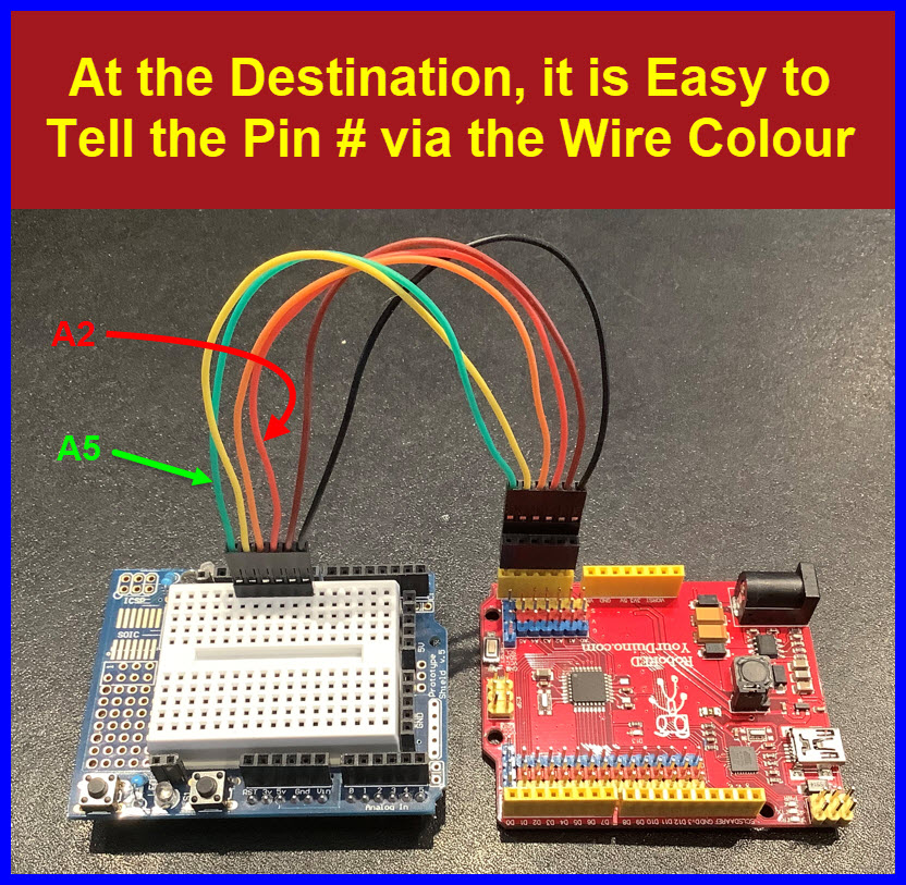
Assembled project is cat proof. Note that its still running after being shoved 1/2 off the table by the cat. None of the connections came loose. Note that the DuPont connectors have retention shrouds that give a place to label, id pin #1, color code to match, group for easier insertion and less susceptible to vibration.