So I'm not sure if this is a common occurrence in pcbs or maybe in very small scale pcbs, or if ones I'm showing are just more budget level of design.
Can anybody help me with feedback on my two possible ways provided in terms of it being a extreme No-No that I'm not aware of because of a beginner state.
Also if anyone can explain why it would be a No-No or if it actually is fine to do, as well as any other suggestions on being able to secure these types of through holes without resorting to an absolute permanent adjustment such as glueing the entire board or some other permanent method.
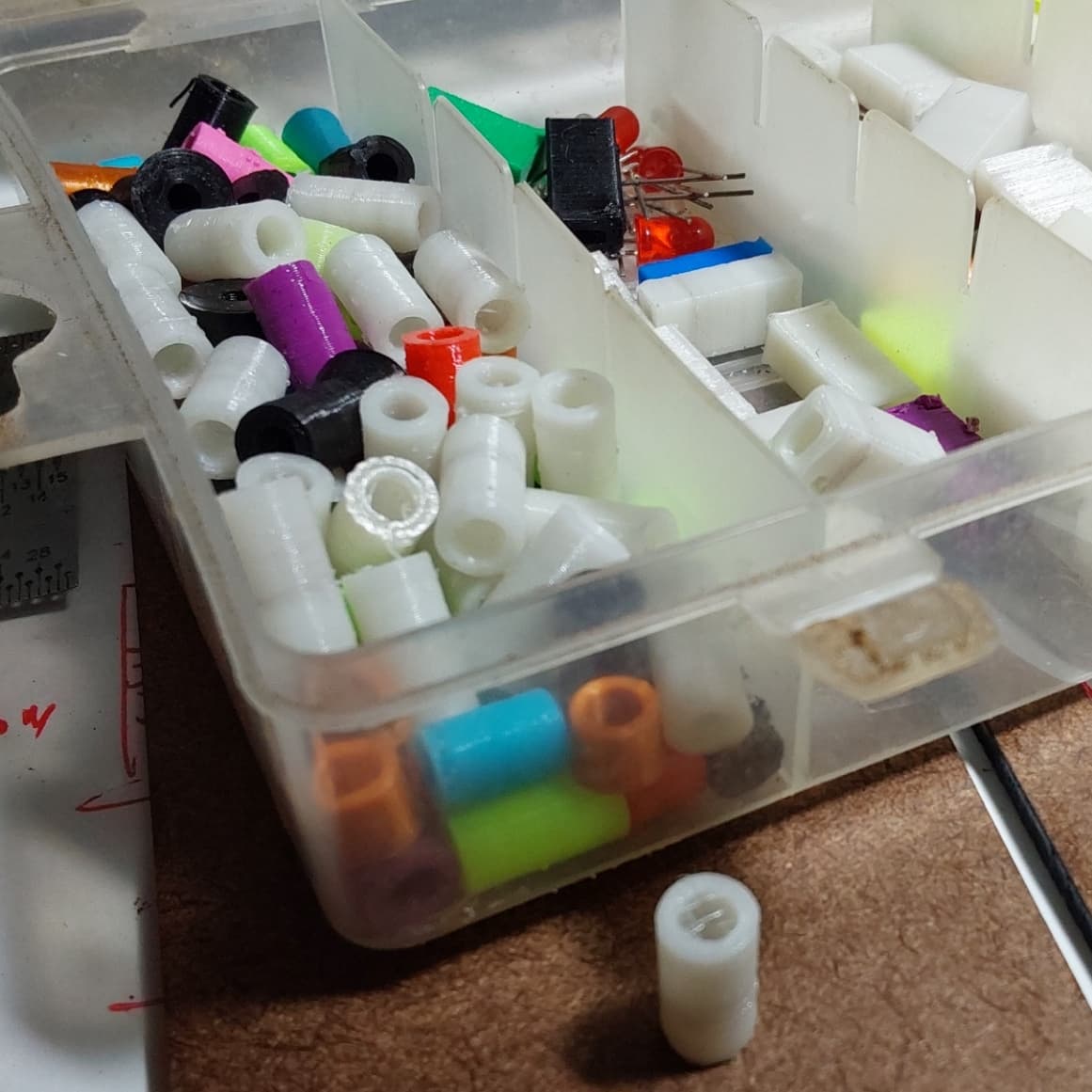
This is a picture is showing the mounting holes that have metal inserts that are unthreaded

This one looks to have 4 mounting holes, but tge inner 2 are clearly merged with an other component.

The two bolts in the picture beside the boards I am able to very carefully line up and slowly turn it in and it creates a snug tight fit and I'm able to carefully unscrew it and there seems to be a slight formation of the threads allowing me to put it back in a little bit more smoothly.
Is it okay to do this with the metal through hole mounting spots? If I was to use isopropylene and a air duster to gently blow away any metal flakes that may have come off?
An alternative to doing it this way is my idea of this:
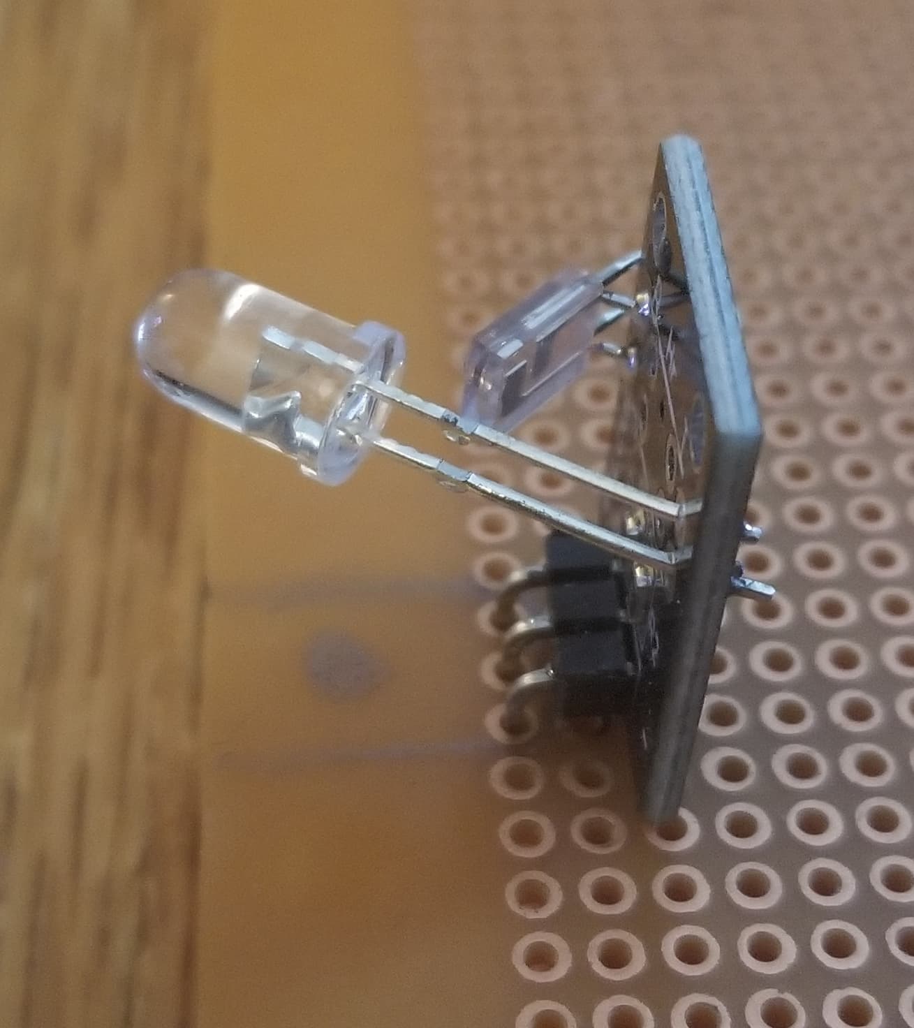

Taking a breadboard that's meant for actual soldering and then cutting out a little chunk on the edge such as where I marked so that I can solder this junk to the pins on the component with having a little hole drilled out in the mark spot prior to the soldering that is providing ample room for washers and bolt heads.
Then on the other side I could take these male breadboard jumper pins and cut the wire off a quarter of an inch or so away and then solder it to the pin on the bottom and crazy glue the three jumper bodies together to replace the perfectly aligned three horizontal pins that can go into a breadboard or controller directly.
I don't consider this to be an extreme permanent method as I've used solderwick on much more complex Corrections so I feel at a beginner level this is an easy method of being able to return to default if needed.
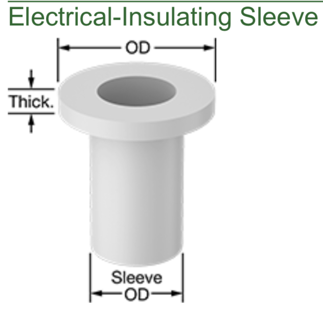
Mounting holes like this that are not manufactured with an included metal insert and are like the previous or even worse leaving you absolutely no clearance for a washer or head.
Without resulting to a 3D printed custom enclosure what could I do to make use of this Mounting hole that will allow me to use it with a better supporting method then just having a nipple that will not hold it in place if it tips upside down.
This hole is on an UNO R3 compatible clone model that I picked up for ease of mind allow me to not shortout the proper boards that cost quite a bit more which came as the controller in some of the kits.
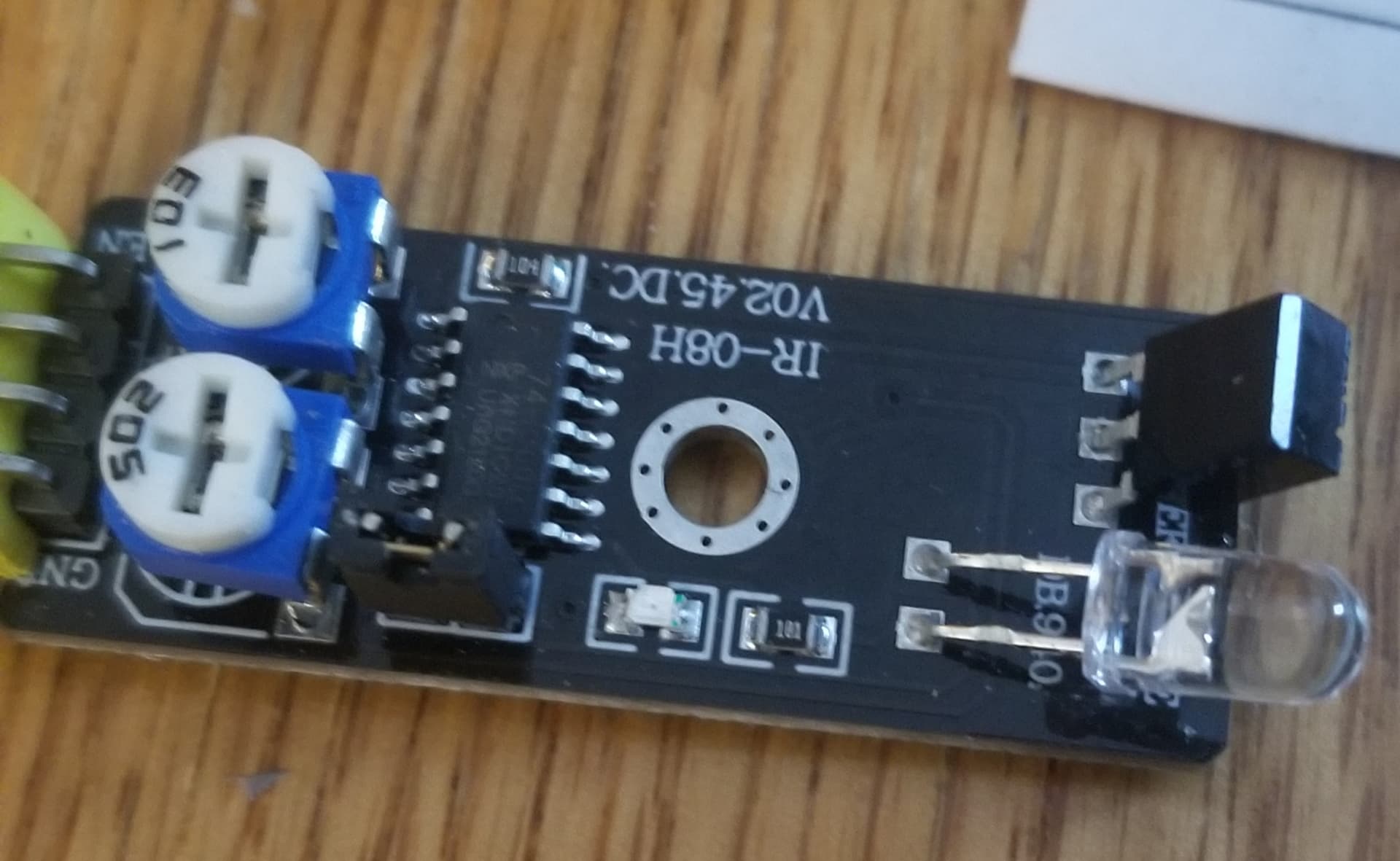
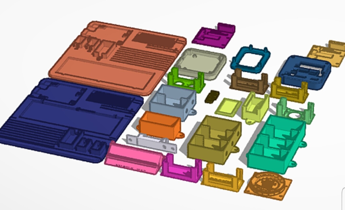
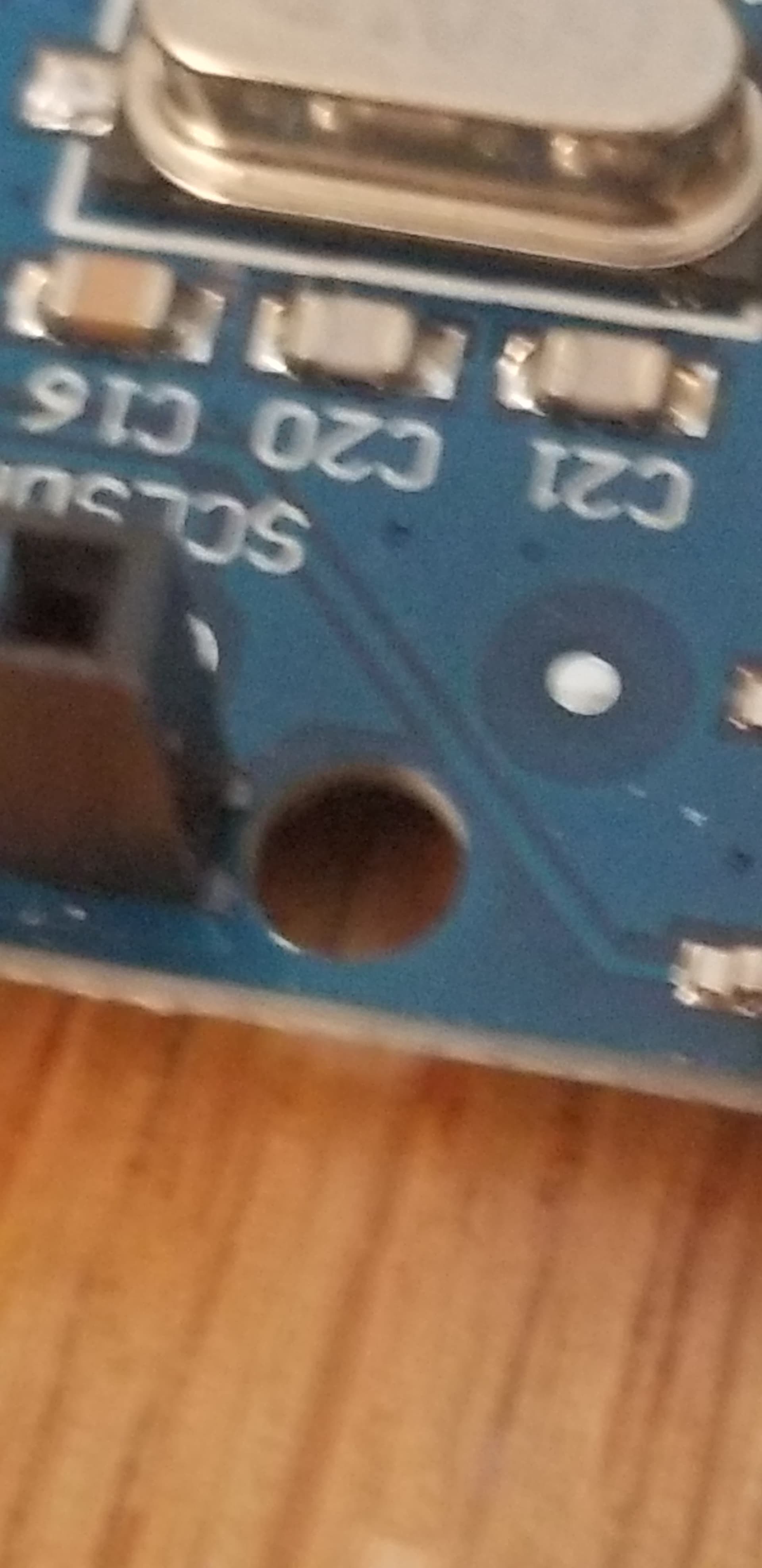
And finally some of the modules like this only have a single hole somewhere that is quite large and gives off the feeling it is a functional aspect of the board and not meant for shoving a bolt through, is that correct or is this actually a mounting hole?
I know 3D printing an enclosure designed for this specific component is probably what most people are going to generally recommend, but I just don't have access to a 3D printer to make something for this scale because of minimum print costs required and the amount of time it would take to 3D model the enclosure of such a case when I have at least 28 different little boards like this that all have similar holes for diameter but zero consistency in the spacing and Alignment between the various holes and location from the edges.
Any other suggestions on mounting this type of very small scale piece please try to keep a concept that you can undo without damaging the board at a beginner level, as I'm trying to make these pieces still work on a breadboard but also conveniently able to fasten on to some kind of a rail or Surface.
Thank you very much for your time to read this.