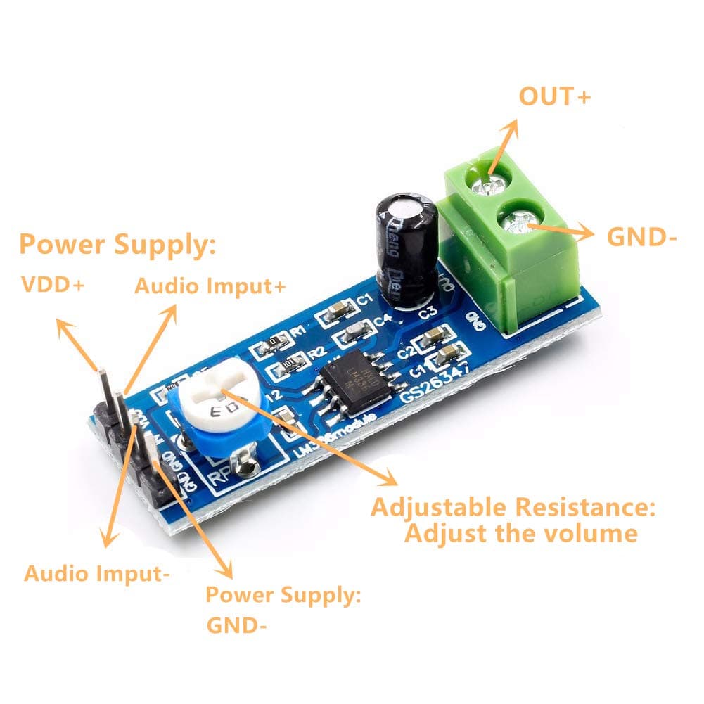
Hey all,
I'm having an issue in which a speaker is outputting sound, but it is very quiet. I cannot for the life of me figure out why. Here is the circuit diagram:
The speaker is 4 ohms, 3 watts. The transistor is a 2N3904, but I don't think that's the issue because it works the same without it (except for the fact that the amplifier explodes when it recieves current through Vcc and not Vin).
Does anyone have experience with this amplifier? It seems to be a pretty common budget option on Amazon. Thank you!
For output full power, remove the transistor and 100 Ohm resistor in the amplifier power supply lead. I'm surprised that that works at all. What does the short circuit connection do?
If you want to control power to the amplifier, use a Pololu power switch instead.a
BTW you never know what you are getting from cheap resellers on Amazon and eBay, but sometimes the stuff works as advertised.
It's unclear what is on the amp pcb other than the chip, but the chip input is ground referenced (if it is LM386) and it would work best if there was a coupling capacitor between the audio input and the Arduino pin.
Tested it; the sound is exactly the same either way. How would a power switch work differently/better than a transistor? I want it to be controlled by the arduino, not any physical switch.
Please post the correct schematic. The posted schematic short circuits the battery through the transistor and resistor, and the amplifier is not powered at all.
Could the issue be that my speaker is rated for 3 watts and the LM386 module is only outputting 700mW? Would using a 1 watt or less speaker be louder, or basically the same?
My understanding is that, without that resistor, the transistor blows up. This is the diagram I was immatating when constucting this:
Looking at it now, mine doesn't really look like it does the same thing. In any case, I don't think it should be affecting the volume, as bypassing the transistor entirely produces the same volume.
Everything you have posted makes sense, except your expectations. None of the posted circuits will work.
Get rid of the transistor and resistor, and power the amplifier with 6V. Connect all the grounds, and connect the Arduino output to the amplifier input using a capacitor (1 to 10 uF). You may need to add a volume control (10 K potentiometer).
Just out of curiosity, what will the capacitor do? Trying to learn as much as I can.
Also, the amplifier circuit came with both a 10k pot and a 10uF capacitor on it already. Is it logical to assume they are already confiugred in the correct way?
The capacitor blocks the DC voltage on the input, which will prevent the amplifier from working.
Then you are all set, except that you need to power the amplifier correctly. That requires you to remove the transistor and resistor from the power lead.
I don't think we can assume that the capacitor is at the input - the only big cap is at the output end, and at the input end it looks very much like there's no input coupling capacitor though there is a pot which is for gain (volume) control. Mind you, 10uF doesn't seem like big enough for speaker coupling, are you sure it isn't 100uF? (I'd use much more.)
Looking at the LM386 data sheet the input is "ground referenced" which is nice for many audio applications because no coupling cap will be needed to block the DC level. However in your schematic you are connecting directly to a digital output pin which at best will have an average bias of 2.5v (half 5v rail) (or 1.65v with 3.3v supply) - this means that the amplifier will be biased completely out of its linear range except when the pin pulses low. I assume you are only expecting to send it tone square waves? Given that the amp has a gain of 20, you should drive it from a potential divider of at least 10:1 from the Arduino pin (say 10k from the pin to the amp input and 1k from input to Gnd, with a capacitor in series with the 10k to block the DC level). Assuming say that the Arduino is outputting a square wave, the input will then be an 0.25v peak square wave and you can turn down the volume pot. It doesn't matter what speaker you use provided its impedance is about right - TI recommend 4 ohm, 8 ohm would be a bit quieter. A bigger speaker with a higher watt rating would probably sound louder as it should be more efficient.
The capacitor definitely says 10 uF on it. Beyond that, I have no idea as to it’s purpose.
I’m actually planning on using the talkie library to output speech-like audio, not square waves, but I’d imagine your advice applies similarly, right?
Does the value of the resistors matter, or just their ratio? I have a 100 ohm and a 1k ohm, but no 10k ohm, so if I could I’d rather just use the 100 and the 1k.
Well I think it's the output coupling capacitor. This is needed because the output pin sits at a quiescent voltage of Vcc/2, and if the speaker was connected to it directly that would be shorted to ground. The cap blocks the DC but lets the ac signals you want through. I just think it's ridiculously small -
TI's data sheet suggests 250uF! 10uF would give a lower cutoff frequency with a 4 ohm speaker of ~4kHz! If you're trying to listen to a lower frequency no wonder it sounds quiet!
Just the resistor ratio is important.
I'm not familiar with that library but not sure how you get audio through a digital output pin!
If you use this to drive a 2 inch speaker, the cap value might be just right to filter out the lower tones that would otherwise rip apart the speaker...
If you have a serious speaker, the value is indeed too low...