Hello,
I am trying to use LowPowerLab's RFM69 library, but I can't get past the initialization. I have gotten RadioHead examples to work, so the problem shouldn't be soldering or the antenna.
I have an Adafruit RFM69HCW module connected to an Arduino Uno like so:

The Adafruit breakout board has logic level converters on all the pins, so they're connected directly to the Uno.
This is the code I'm running:
#include <RFM69.h>         //get it here: https://www.github.com/lowpowerlab/rfm69
#include <RFM69_ATC.h>     //get it here: https://github.com/lowpowerlab/RFM69
#include <SPI.h>           //included with Arduino IDE (www.arduino.cc)
#include <LowPower.h>      //get library from: https://github.com/lowpowerlab/lowpower

//****************************************************************************************************************
//**** IMPORTANT RADIO SETTINGS - YOU MUST CHANGE/CONFIGURE TO MATCH YOUR HARDWARE TRANSCEIVER CONFIGURATION! ****
//****************************************************************************************************************
#define NETWORKID     0  //the same on all nodes that talk to each other
#define RECEIVER      1    //unique ID of the gateway/receiver
#define SENDER        2
#define NODEID        SENDER  //change to "SENDER" if this is the sender node (the one with the button)
//Match frequency to the hardware version of the radio on your Moteino (uncomment one):
#define FREQUENCY     RF69_433MHZ
#define ENCRYPTKEY    "sampleEncryptKey" //exactly the same 16 characters/bytes on all nodes!
#define IS_RFM69HW_HCW  //uncomment only for RFM69HW/HCW! Leave out if you have RFM69W/CW!
//*****************************************************************************************************************************
//#define ENABLE_ATC      //comment out this line to disable AUTO TRANSMISSION CONTROL
#define ATC_RSSI        -75
//*********************************************************************************************
#define SERIAL_BAUD   9600


#ifdef ENABLE_ATC
  RFM69_ATC radio;
#else
  RFM69 radio;
#endif

void setup() {
  Serial.begin(SERIAL_BAUD);

  if(!radio.initialize(FREQUENCY,NODEID,NETWORKID)){
    Serial.println("init failed");
    while(1);
  }
  Serial.println("radio successfully initiated");
}
I have changed the library's initialize() function like so:
bool RFM69::initialize(uint8_t freqBand, uint16_t nodeID, uint8_t networkID) {
  _interruptNum = digitalPinToInterrupt(_interruptPin);

  if (_interruptNum == (uint8_t)NOT_AN_INTERRUPT) return false;
#ifdef RF69_ATTACHINTERRUPT_TAKES_PIN_NUMBER
    _interruptNum = _interruptPin;
#endif
  const uint8_t CONFIG[][2] = {
    /* 0x01 */ { REG_OPMODE, RF_OPMODE_SEQUENCER_ON | RF_OPMODE_LISTEN_OFF | RF_OPMODE_STANDBY },
    /* 0x02 */ { REG_DATAMODUL, RF_DATAMODUL_DATAMODE_PACKET | RF_DATAMODUL_MODULATIONTYPE_FSK | RF_DATAMODUL_MODULATIONSHAPING_00 }, // no shaping
    /* 0x03 */ { REG_BITRATEMSB, RF_BITRATEMSB_55555}, // default: 4.8 KBPS
    /* 0x04 */ { REG_BITRATELSB, RF_BITRATELSB_55555},
    /* 0x05 */ { REG_FDEVMSB, RF_FDEVMSB_50000}, // default: 5KHz, (FDEV + BitRate / 2 <= 500KHz)
    /* 0x06 */ { REG_FDEVLSB, RF_FDEVLSB_50000},

    /* 0x07 */ { REG_FRFMSB, (uint8_t) (freqBand==RF69_315MHZ ? RF_FRFMSB_315 : (freqBand==RF69_433MHZ ? RF_FRFMSB_433 : (freqBand==RF69_868MHZ ? RF_FRFMSB_868 : RF_FRFMSB_915))) },
    /* 0x08 */ { REG_FRFMID, (uint8_t) (freqBand==RF69_315MHZ ? RF_FRFMID_315 : (freqBand==RF69_433MHZ ? RF_FRFMID_433 : (freqBand==RF69_868MHZ ? RF_FRFMID_868 : RF_FRFMID_915))) },
    /* 0x09 */ { REG_FRFLSB, (uint8_t) (freqBand==RF69_315MHZ ? RF_FRFLSB_315 : (freqBand==RF69_433MHZ ? RF_FRFLSB_433 : (freqBand==RF69_868MHZ ? RF_FRFLSB_868 : RF_FRFLSB_915))) },

    // looks like PA1 and PA2 are not implemented on RFM69W/CW, hence the max output power is 13dBm
    // +17dBm and +20dBm are possible on RFM69HW
    // +13dBm formula: Pout = -18 + OutputPower (with PA0 or PA1**)
    // +17dBm formula: Pout = -14 + OutputPower (with PA1 and PA2)**
    // +20dBm formula: Pout = -11 + OutputPower (with PA1 and PA2)** and high power PA settings (section 3.3.7 in datasheet)
    ///* 0x11 */ { REG_PALEVEL, RF_PALEVEL_PA0_ON | RF_PALEVEL_PA1_OFF | RF_PALEVEL_PA2_OFF | RF_PALEVEL_OUTPUTPOWER_11111},
    ///* 0x13 */ { REG_OCP, RF_OCP_ON | RF_OCP_TRIM_95 }, // over current protection (default is 95mA)

    // RXBW defaults are { REG_RXBW, RF_RXBW_DCCFREQ_010 | RF_RXBW_MANT_24 | RF_RXBW_EXP_5} (RxBw: 10.4KHz)
    /* 0x19 */ { REG_RXBW, RF_RXBW_DCCFREQ_010 | RF_RXBW_MANT_16 | RF_RXBW_EXP_2 }, // (BitRate < 2 * RxBw)
    //for BR-19200: /* 0x19 */ { REG_RXBW, RF_RXBW_DCCFREQ_010 | RF_RXBW_MANT_24 | RF_RXBW_EXP_3 },
    /* 0x25 */ { REG_DIOMAPPING1, RF_DIOMAPPING1_DIO0_01 }, // DIO0 is the only IRQ we're using
    /* 0x26 */ { REG_DIOMAPPING2, RF_DIOMAPPING2_CLKOUT_OFF }, // DIO5 ClkOut disable for power saving
    /* 0x28 */ { REG_IRQFLAGS2, RF_IRQFLAGS2_FIFOOVERRUN }, // writing to this bit ensures that the FIFO & status flags are reset
    /* 0x29 */ { REG_RSSITHRESH, 220 }, // must be set to dBm = (-Sensitivity / 2), default is 0xE4 = 228 so -114dBm
    ///* 0x2D */ { REG_PREAMBLELSB, RF_PREAMBLESIZE_LSB_VALUE } // default 3 preamble bytes 0xAAAAAA
    /* 0x2E */ { REG_SYNCCONFIG, RF_SYNC_ON | RF_SYNC_FIFOFILL_AUTO | RF_SYNC_SIZE_2 | RF_SYNC_TOL_0 },
    /* 0x2F */ { REG_SYNCVALUE1, 0x2D },      // attempt to make this compatible with sync1 byte of RFM12B lib
    /* 0x30 */ { REG_SYNCVALUE2, networkID }, // NETWORK ID
    //* 0x31 */ { REG_SYNCVALUE3, 0xAA },
    //* 0x31 */ { REG_SYNCVALUE4, 0xBB },
    /* 0x37 */ { REG_PACKETCONFIG1, RF_PACKET1_FORMAT_VARIABLE | RF_PACKET1_DCFREE_OFF | RF_PACKET1_CRC_ON | RF_PACKET1_CRCAUTOCLEAR_ON | RF_PACKET1_ADRSFILTERING_OFF },
    /* 0x38 */ { REG_PAYLOADLENGTH, 66 }, // in variable length mode: the max frame size, not used in TX
    ///* 0x39 */ { REG_NODEADRS, nodeID }, // turned off because we're not using address filtering
    /* 0x3C */ { REG_FIFOTHRESH, RF_FIFOTHRESH_TXSTART_FIFONOTEMPTY | RF_FIFOTHRESH_VALUE }, // TX on FIFO not empty
    /* 0x3D */ { REG_PACKETCONFIG2, RF_PACKET2_RXRESTARTDELAY_2BITS | RF_PACKET2_AUTORXRESTART_OFF | RF_PACKET2_AES_OFF }, // RXRESTARTDELAY must match transmitter PA ramp-down time (bitrate dependent)
    //for BR-19200: /* 0x3D */ { REG_PACKETCONFIG2, RF_PACKET2_RXRESTARTDELAY_NONE | RF_PACKET2_AUTORXRESTART_ON | RF_PACKET2_AES_OFF }, // RXRESTARTDELAY must match transmitter PA ramp-down time (bitrate dependent)
    /* 0x6F */ { REG_TESTDAGC, RF_DAGC_IMPROVED_LOWBETA0 }, // run DAGC continuously in RX mode for Fading Margin Improvement, recommended default for AfcLowBetaOn=0
    {255, 0}
  };

  digitalWrite(_slaveSelectPin, HIGH);
  pinMode(_slaveSelectPin, OUTPUT);

  Serial.println(_slaveSelectPin);

  //-------------------------------new------------------------------------------------
 // borrowed from the Radiohead library's init function:
  //get device type and check it
  //test if we really are connected to a device
  int deviceType = readReg(REG_VERSION);
  if (deviceType == 00 || deviceType == 0xff){
    Serial.println("device type not acceptable");
    //return false;
  }
//--------------------------------------------------------------------------------

  if(_spi == nullptr){
    _spi = &SPI;
  }
  _spi->begin();

#ifdef SPI_HAS_TRANSACTION
  _settings = SPISettings(8000000, MSBFIRST, SPI_MODE0);
#endif

  uint32_t start = millis();
  uint8_t timeout = 50;

//--------- new ---------------------------------------------------------------------------
//keeping this while loop going so that I can debug the hw connections:

  do writeReg(REG_SYNCVALUE1, 0xAA); while (readReg(REG_SYNCVALUE1) != 0xaa); //&& millis()-start < timeout);
//-----------------------------------------------------------------------------------------

  if (millis()-start >= timeout) {
    return false;
  }
  start = millis();
  do writeReg(REG_SYNCVALUE1, 0x55); while (readReg(REG_SYNCVALUE1) != 0x55 && millis()-start < timeout);
  if (millis()-start >= timeout) {
    return false;
  }
  for (uint8_t i = 0; CONFIG[i][0] != 255; i++)
    writeReg(CONFIG[i][0], CONFIG[i][1]);

  // Encryption is persistent between resets and can trip you up during debugging.
  // Disable it during initialization so we always start from a known state.
  encrypt(0);

  setHighPower(_isRFM69HW); // called regardless if it's a RFM69W or RFM69HW (at this point _isRFM69HW may not be explicitly set by constructor and setHighPower() may not have been called yet (ie called after initialize() call)
  setMode(RF69_MODE_STANDBY);
  start = millis();
  while (((readReg(REG_IRQFLAGS1) & RF_IRQFLAGS1_MODEREADY) == 0x00) && millis()-start < timeout); // wait for ModeReady
  if (millis()-start >= timeout){
    return false;
  }
  attachInterrupt(_interruptNum, RFM69::isr0, RISING);

  _address = nodeID;
#if defined(RF69_LISTENMODE_ENABLE)
  selfPointer = this;
  _freqBand = freqBand;
  _networkID = networkID;
#endif
  return true;
}
Now what happens is that reading the REG_VERSION register should have returned 42 had there been an SPI connection, according to the RadioHead library's init function. It returns 0.
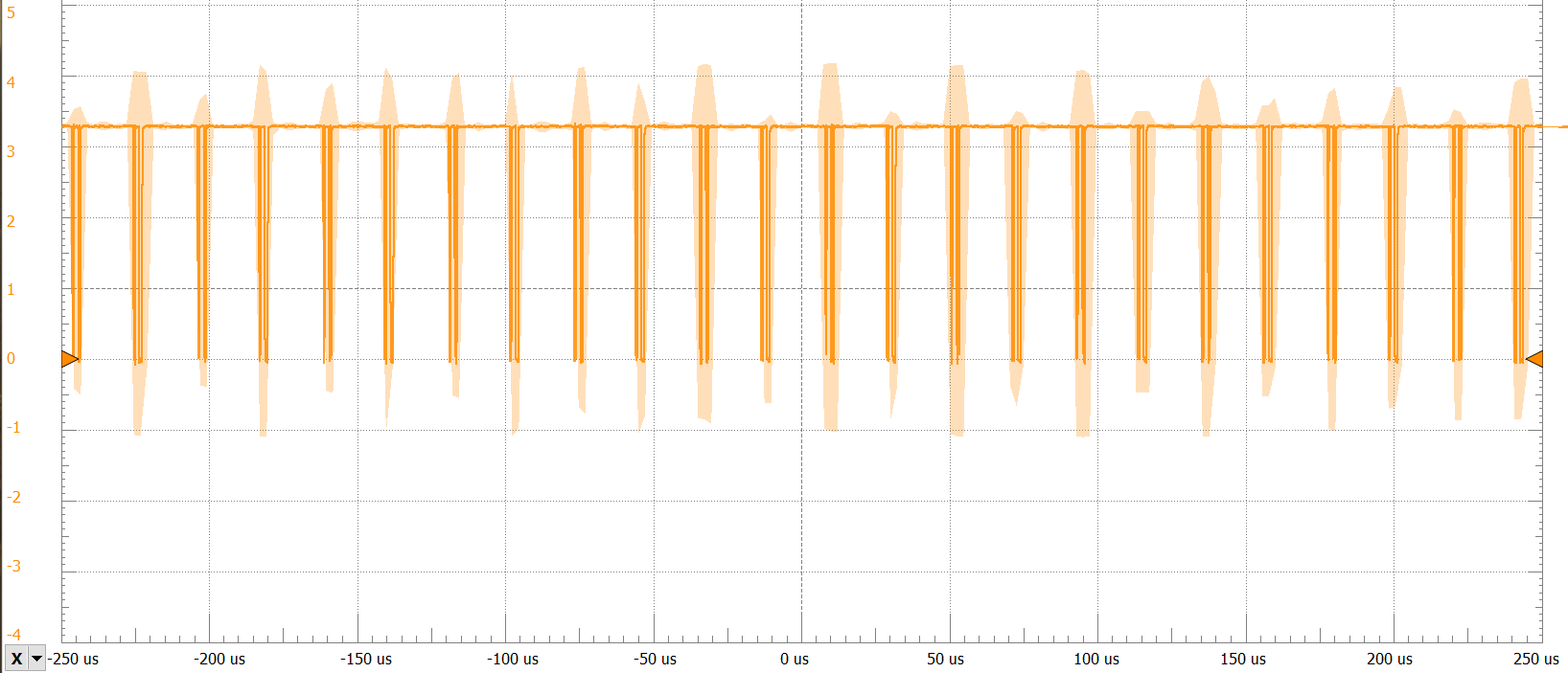
I scoped the spi pins on the RFM69HCW and discovered that the MISO pin gave a very small signal:

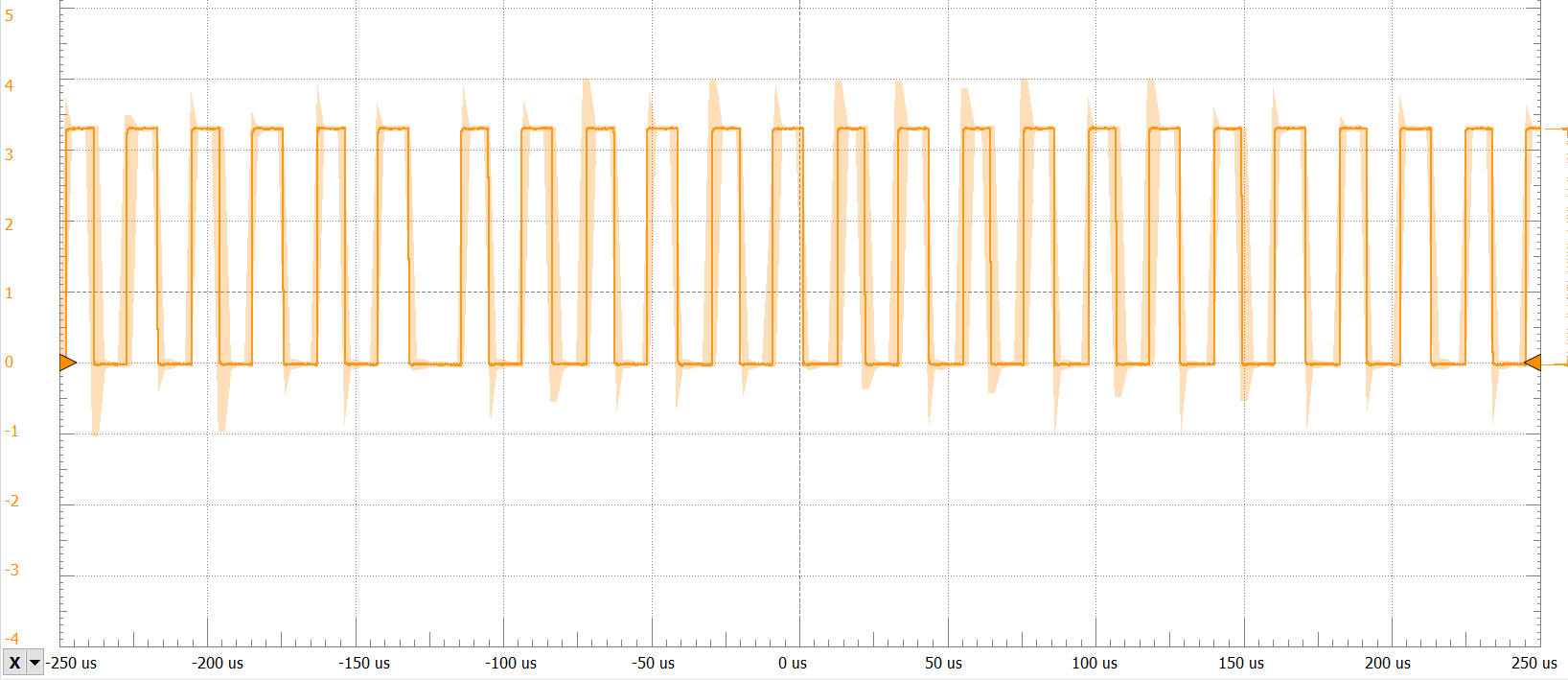
compared to when I did the same using the RadioHead library:

The MOSI pin looked like this:
SCK:

NSS:
Any idea what could be the problem? Help would be very much appreciated ![]()