SPI interface of ESP32-C6 SuperMini

I have a esp32-c6 supermini from TZT. This board:
https://www.tztstore.com/goods/show-7996.html

I want to connect a ST7789 1.3 oled display (240x240) to this module.
My display board does not have CS pin, so I understand that I should initialize the display with:
Adafruit_ST7789 tft = Adafruit_ST7789(TFT_CS, TFT_DC, TFT_MOSI, TFT_SCLK, TFT_RST);
tft.init(240, 240, SPI_MODE3);

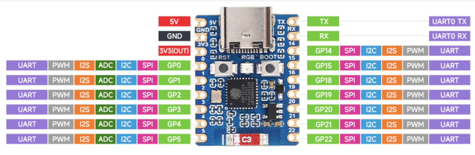
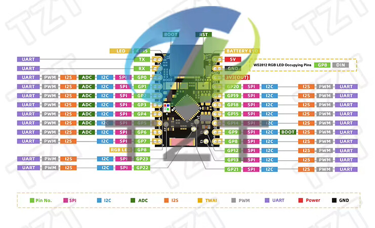
But I don't know which pins I have to use for SCL and MOSI on esp32-c6 supermini.
How can I find the correct pins ?

I followed :

But I need MOSI/SCL pins.

Thanks.

I expect you can use any gpio pins, but try if it defaults to gpio6 and 7.

The board datasheet is the usual method, but I bet this is a modern board and almost any pin can be used.
I used google and found this.


I also thought so, and defined as:

#define TFT_CS        4
#define TFT_RST        3 
#define TFT_DC         5
#define TFT_MOSI 7  
#define TFT_SCLK 6  

Adafruit_ST7789 tft = Adafruit_ST7789(TFT_CS, TFT_DC, TFT_MOSI, TFT_SCLK, TFT_RST);

tft.init(240, 240, SPI_MODE3);

But all I get is a resetting black screen.
The display receives power I can see its backlit but there is nothing on the display.
what am I doing wrong ?

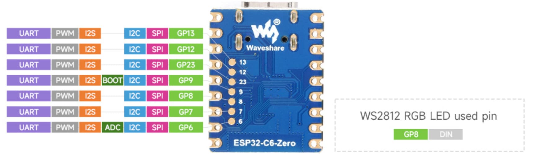
when I change the SCL to 9 and MOSI to 6 , screen turns white after black.
If I change SCL to 9 and MOSI to 8 , screen stays black BUT the onboard led turns on (first green then white)
interesting ?

if I don't set MOSI and SCK when initializing tft , I read in serial:

2:55:52.276 -> GPIO Info:
22:55:52.276 -> ------------------------------------------
22:55:52.276 -> GPIO : BUS_TYPE[bus/unit][chan]
22:55:52.276 -> --------------------------------------
22:55:52.276 -> 3 : GPIO
22:55:52.276 -> 4 : GPIO
22:55:52.276 -> 5 : GPIO
22:55:52.276 -> 12 : USB_DM
22:55:52.276 -> 13 : USB_DP
22:55:52.276 -> 16 : UART_TX[0]
22:55:52.276 -> 17 : UART_RX[0]
22:55:52.276 -> 19 : SPI_MASTER_MOSI[0]
22:55:52.276 -> 20 : SPI_MASTER_MISO[0]
22:55:52.276 -> 21 : SPI_MASTER_SCK[0]
22:55:52.276 -> ============ After Setup End =============

But there is no PIN 21 on this board ???

I found the PIN 21. It is in the middle of the board.
So if I don't set MOSI and SCK it defaults to :

22:55:52.276 -> 19 : SPI_MASTER_MOSI[0]
22:55:52.276 -> 20 : SPI_MASTER_MISO[0]
22:55:52.276 -> 21 : SPI_MASTER_SCK[0]

But I really don't prefer to use that PIN 21.
Can I change it to something else ?
Why doesn't the following command work:
Adafruit_ST7789 tft = Adafruit_ST7789(TFT_CS, TFT_DC, TFT_MOSI, TFT_SCLK, TFT_RST);

Find and read the datasheet for the display, the esp32. Check github for any documentation. The easiest way is to open Library Manager, find the library and beside the name is 3 periods. Click that and navigate to the example sketches.
If that doesn't work your wiring is wrong do post the entire sketch and a hand drawn wiring diagram.

if I don't set MOSI and SCK manually, it defaults to 19 and 21 and if I wire to these ports , it works fine.
I just don't prefer to use the PIN 21.
How can I change SCK to another PIN ?

Probably in the begin or init methods, but if I can't see the code I can't tell you. Look at the begin and init member functions in the library, or just hover the cursor over the begin or init statement. You may need to do a compile first, and it won;t hurt to do a highlight the library hdr and rt click then goto definition. I am including the goto definition screen grabs. The last one is the read-only tab now open in your sketch.


I really didn't understand what you meant. Did you read what I wrote ?
Code works. If I don't set the MOSI and SCK explicitly in Adafruit_ST7789 definition, and if I use PINS 19 & 21 it WORKS.
I am asking if it is possible to change the default PINS (19 and 21) because you wrote above:
"but I bet this is a modern board and almost any pin can be used."

Yes I read.
Yes it's possible.
Adafruit_ST7789(int8_t cs, int8_t dc, int8_t mosi, int8_t sclk,
int8_t rst = -1);

@brief  Instantiate Adafruit ST7789 driver with software SPI
@param  cs    Chip select pin #
@param  dc    Data/Command pin #
@param  mosi  SPI MOSI pin #
@param  sclk  SPI Clock pin #
@param  rst   Reset pin # (optional, pass -1 if unused)

no you are not reading. If you have read, you would see above that I already tried that syntax and it did not work.

That is the correct syntax, I got it from the source code. You have some other problem.

ok. maybe this board is not so modern at all.
maybe the SCK and MOSI are not choosable.

Or a fake clone. How many pins did you try?

it is not a fake clone. All pins are working. I can use pins 3,4,5,6,7,8,9 for other purposes. But when I set SCK or MOSI to one of these PINS , it does not work.
Maybe the library needs some other option to be set.

Post #3 shows all the pins available for SPI.

that is Waveshare's esp-c6-zero board. Mine is TZT's esp-c6-supermini

Doesn't change much, concerning SPI interfaces.
Maybe these 2 topics can help you, although not the same board either:

https://forum.arduino.cc/t/cannot-configure-my-st7789-screen-with-esp32-c3-super-mini/

https://forum.arduino.cc/t/how-to-connect-st7789-display-to-esp32-c3-supermini/