SSD1306 OLED Display module not working

Hi. I bought the following OLED display:

I am using an UNO copy.

First I wired it up as described on the sellers page on Aliexpress, and followed their instructions regarding installing the u8g2 library and I copied their example code, all included in the link above.
When I upload the code nothing happens.

Then I followed the instructions described here:

I installed all the libraries and followed all the instructions, except when I run any code to find the I2C's address I run in to an error.
The Serial monitor only writes "I2C Scanner Scanning..." and nothing more. When I press the reset button on the Ardurino it writes the same message again, but that's all.

I used the A5 pin to control a relay earlier, so the pin itself should work fine in theory.

Do you have any idea what could be the issue here?
If I missed any detail you need for helping please ask and thank you for any input!

P.s.: I run into the same issue when I try to find the address of an I2C module soldered to the basic 2 row LCD screen which comes with the basic kit. (and when I wire this setup and power it all I get is the back light and the first row is on with solid bars)

Welcome to the forum

Please post the code here, using code tags (the </> icon) when you do

Hi, Thanks for the welcome!

So the code I used for the u8g2 approach is:

#include <Arduino.h>
#include <U8g2lib.h>

#ifdef U8X8_HAVE_HW_SPI
#include <SPI.h>
#endif
#ifdef U8X8_HAVE_HW_I2C
#include <Wire.h>
#endif

U8G2_SSD1306_128X64_NONAME_F_SW_I2C u8g2(U8G2_R0,A5,A4,U8X8_PIN_NONE);

void setup(void) {
  u8g2.begin();
}

void loop(void) {
  u8g2.clearBuffer();
  u8g2.setFont(u8g2_font_ncenB08_tr);
  u8g2.drawStr(0,10,"ideaspark 0.96'' OLED");
  u8g2.drawStr(0,25,"0.96");
  u8g2.drawStr(0,35,"0.96 inch");
  u8g2.drawStr(0,45,"0.96 inch OLED");
  u8g2.drawStr(0,55,"0.96 inch OLED 128x64");
  u8g2.sendBuffer();
  delay(1000);
}

The code I used for the ArdurinoGetStarted approach is:


#include <Wire.h>
#include <Adafruit_GFX.h>
#include <Adafruit_SSD1306.h>

#define SCREEN_WIDTH 128 // OLED display width,  in pixels
#define SCREEN_HEIGHT 64 // OLED display height, in pixels

// declare an SSD1306 display object connected to I2C
Adafruit_SSD1306 oled(SCREEN_WIDTH, SCREEN_HEIGHT, &Wire, -1);

void setup() {
  Serial.begin(9600);

  // initialize OLED display with address 0x3C for 128x64
  if (!oled.begin(SSD1306_SWITCHCAPVCC, 0x3C)) {
    Serial.println(F("SSD1306 allocation failed"));
    while (true);
  }

  delay(2000); // wait for initializing
  oled.setCursor(0, 0);
}

void loop() {
  // draw rectangle
  oled.clearDisplay();
  oled.drawRect(0, 15, 60, 40, WHITE);
  oled.display();
  delay(2000);

  // fill rectangle
  oled.clearDisplay();
  oled.fillRect(0, 15, 60, 40, WHITE);
  oled.display();
  delay(2000);


  // draw the round rectangle
  oled.clearDisplay();
  oled.drawRoundRect(0, 15, 60, 40, 8, WHITE);
  oled.display();
  delay(2000);

  // fill the round rectangle
  oled.clearDisplay();
  oled.fillRoundRect(0, 15, 60, 40, 8, WHITE);
  oled.display();
  delay(2000);

  // draw circle
  oled.clearDisplay();
  oled.drawCircle(20, 35, 20, WHITE);
  oled.display();
  delay(2000);

  // fill circle
  oled.clearDisplay();
  oled.fillCircle(20, 35, 20, WHITE);
  oled.display();
  delay(2000);

  // draw triangle
  oled.clearDisplay();
  oled.drawTriangle(30, 15, 0, 60, 60, 60, WHITE);
  oled.display();
  delay(2000);

  // fill triangle
  oled.clearDisplay();
  oled.fillTriangle(30, 15, 0, 60, 60, 60, WHITE);
  oled.display();
  delay(2000);
}

and the code I used to scan for the I2C address is:

// I2C address scanner program

#include <Wire.h>

void setup()
{
  Wire.begin();
  Serial.begin(9600);
  Serial.println("I2C Scanner");
}

void loop()
{
  byte error, address;
  int nDevices;

  Serial.println("Scanning...");

  nDevices = 0;
  for(address = 1; address < 127; address++ )
  {
    Wire.beginTransmission(address);
    error = Wire.endTransmission();

    if (error == 0)
    {
      Serial.print("I2C device found at address 0x");
      if (address < 16)
        Serial.print("0");

      Serial.print(address,HEX);
      Serial.println("  !");

      nDevices++;
    }
    else if (error==4)
    {
      Serial.print("Unknown error at address 0x");
      if (address < 16)
        Serial.print("0");

      Serial.println(address,HEX);
    }
  }

  if (nDevices == 0)
    Serial.println("No I2C devices found");
  else
    Serial.println("done");

  delay(5000); // wait 5 seconds for next scan
}

Thanks for posting the code here. It really does make it easier to examine and the code tags make it a breeze to copy to an editor

Try this one:

/**
   The MIT License (MIT)

   Copyright (c) 2018 by ThingPulse, Daniel Eichhorn
   Copyright (c) 2018 by Fabrice Weinberg

   Permission is hereby granted, free of charge, to any person obtaining a copy
   of this software and associated documentation files (the "Software"), to deal
   in the Software without restriction, including without limitation the rights
   to use, copy, modify, merge, publish, distribute, sublicense, and/or sell
   copies of the Software, and to permit persons to whom the Software is
   furnished to do so, subject to the following conditions:

   The above copyright notice and this permission notice shall be included in all
   copies or substantial portions of the Software.

   THE SOFTWARE IS PROVIDED "AS IS", WITHOUT WARRANTY OF ANY KIND, EXPRESS OR
   IMPLIED, INCLUDING BUT NOT LIMITED TO THE WARRANTIES OF MERCHANTABILITY,
   FITNESS FOR A PARTICULAR PURPOSE AND NONINFRINGEMENT. IN NO EVENT SHALL THE
   AUTHORS OR COPYRIGHT HOLDERS BE LIABLE FOR ANY CLAIM, DAMAGES OR OTHER
   LIABILITY, WHETHER IN AN ACTION OF CONTRACT, TORT OR OTHERWISE, ARISING FROM,
   OUT OF OR IN CONNECTION WITH THE SOFTWARE OR THE USE OR OTHER DEALINGS IN THE
   SOFTWARE.

   ThingPulse invests considerable time and money to develop these open source libraries.
   Please support us by buying our products (and not the clones) from
   https://thingpulse.com

*/

// Include the correct display library

// For a connection via I2C using the Arduino Wire include:
//#include <Wire.h>               // Only needed for Arduino 1.6.5 and earlier
#include "SSD1306Wire.h"        // legacy: #include "SSD1306.h"
// OR #include "SH1106Wire.h"   // legacy: #include "SH1106.h"
//#include "SH1106Wire.h"   // legacy: #include "SH1106.h"

// For a connection via I2C using brzo_i2c (must be installed) include:
// #include <brzo_i2c.h>        // Only needed for Arduino 1.6.5 and earlier
// #include "SSD1306Brzo.h"
// OR #include "SH1106Brzo.h"

// For a connection via SPI include:
// #include <SPI.h>             // Only needed for Arduino 1.6.5 and earlier
// #include "SSD1306Spi.h"
// OR #include "SH1106SPi.h"


// Optionally include custom images
//#include "images.h"


// Initialize the OLED display using Arduino Wire:
//SSD1306Wire display(0x3c, SDA, SCL);   // ADDRESS, SDA, SCL  -  SDA and SCL usually populate automatically based on your board's pins_arduino.h e.g. https://github.com/esp8266/Arduino/blob/master/variants/nodemcu/pins_arduino.h
SSD1306Wire display(0x3c, D3, D5);  // ADDRESS, SDA, SCL  -  If not, they can be specified manually.
// SSD1306Wire display(0x3c, SDA, SCL, GEOMETRY_128_32);  // ADDRESS, SDA, SCL, OLEDDISPLAY_GEOMETRY  -  Extra param required for 128x32 displays.
//SH1106Wire display(0x3c, SDA, SCL);     // ADDRESS, SDA, SCL

// Initialize the OLED display using brzo_i2c:
// SSD1306Brzo display(0x3c, D3, D5);  // ADDRESS, SDA, SCL
// or
// SH1106Brzo display(0x3c, D3, D5);   // ADDRESS, SDA, SCL

// Initialize the OLED display using SPI:
// D5 -> CLK
// D7 -> MOSI (DOUT)
// D0 -> RES
// D2 -> DC
// D8 -> CS
// SSD1306Spi display(D0, D2, D8);  // RES, DC, CS
// or
// SH1106Spi display(D0, D2);       // RES, DC


#define DEMO_DURATION 3000
typedef void (*Demo)(void);

int demoMode = 0;
int counter = 1;

void setup() {
  Serial.begin(9600);
  Serial.println();
  Serial.println();


  // Initialising the UI will init the display too.
  display.init();

  //display.flipScreenVertically();
  display.setFont(ArialMT_Plain_10);

}

void drawFontFaceDemo() {
  // Font Demo1
  // create more fonts at http://oleddisplay.squix.ch/
  display.setTextAlignment(TEXT_ALIGN_LEFT);
  display.setFont(ArialMT_Plain_10);
  display.drawString(0, 0, "Hello world");
  display.setFont(ArialMT_Plain_16);
  display.drawString(0, 10, "Hello world");
  display.setFont(ArialMT_Plain_24);
  display.drawString(0, 26, "Hello world");
}

void drawTextFlowDemo() {
  display.setFont(ArialMT_Plain_10);
  display.setTextAlignment(TEXT_ALIGN_LEFT);
  display.drawStringMaxWidth(0, 0, 128,
                             "Lorem ipsum\n dolor sit amet, consetetur sadipscing elitr, sed diam nonumy eirmod tempor invidunt ut labore." );
}

void drawTextAlignmentDemo() {
  // Text alignment demo
  display.setFont(ArialMT_Plain_10);

  // The coordinates define the left starting point of the text
  display.setTextAlignment(TEXT_ALIGN_LEFT);
  display.drawString(0, 10, "Left aligned (0,10)");

  // The coordinates define the center of the text
  display.setTextAlignment(TEXT_ALIGN_CENTER);
  display.drawString(64, 22, "Center aligned (64,22)");

  // The coordinates define the right end of the text
  display.setTextAlignment(TEXT_ALIGN_RIGHT);
  display.drawString(128, 33, "Right aligned (128,33)");
}

void drawRectDemo() {
  // Draw a pixel at given position
  for (int i = 0; i < 10; i++) {
    display.setPixel(i, i);
    display.setPixel(10 - i, i);
  }
  display.drawRect(12, 12, 20, 20);

  // Fill the rectangle
  display.fillRect(14, 14, 17, 17);

  // Draw a line horizontally
  display.drawHorizontalLine(0, 40, 20);

  // Draw a line horizontally
  display.drawVerticalLine(40, 0, 20);
}

void drawCircleDemo() {
  for (int i = 1; i < 8; i++) {
    display.setColor(WHITE);
    display.drawCircle(32, 32, i * 3);
    if (i % 2 == 0) {
      display.setColor(BLACK);
    }
    display.fillCircle(96, 32, 32 - i * 3);
  }
}

void drawProgressBarDemo() {
  int progress = (counter / 5) % 100;
  // draw the progress bar
  display.drawProgressBar(0, 32, 120, 10, progress);

  // draw the percentage as String
  display.setTextAlignment(TEXT_ALIGN_CENTER);
  display.drawString(64, 15, String(progress) + "%");
}

void drawImageDemo() {
  // see http://blog.squix.org/2015/05/esp8266-nodemcu-how-to-create-xbm.html
  // on how to create xbm files
//  display.drawXbm(34, 14, WiFi_Logo_width, WiFi_Logo_height, WiFi_Logo_bits);
}

Demo demos[] = {drawFontFaceDemo, drawTextFlowDemo, drawTextAlignmentDemo, drawRectDemo, drawCircleDemo, drawProgressBarDemo, drawImageDemo};
int demoLength = (sizeof(demos) / sizeof(Demo));
long timeSinceLastModeSwitch = 0;

void loop() {
  // clear the display
  display.clear();
  // draw the current demo method
  demos[demoMode]();

  display.setFont(ArialMT_Plain_10);
  display.setTextAlignment(TEXT_ALIGN_RIGHT);
  display.drawString(128, 54, String(millis()));
  // write the buffer to the display
  display.display();

  if (millis() - timeSinceLastModeSwitch > DEMO_DURATION) {
    demoMode = (demoMode + 1)  % demoLength;
    timeSinceLastModeSwitch = millis();
  }
  counter++;
  delay(10);
}
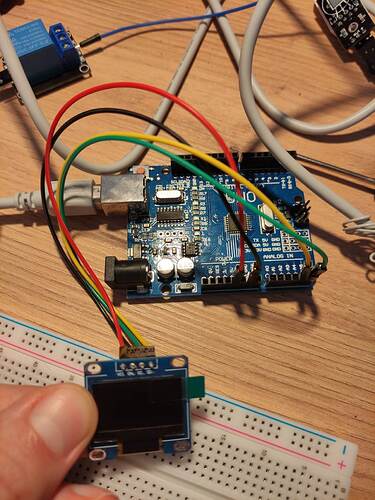
Hi. The problem seems to be that I can not even locate the address of the module. As the I2C address scanner does not work. Looks like the Arduino is not able to communicate with the display maybe?

Maybe verify:

I2C Termination resistors - Using Arduino / Project Guidance - Arduino Forum

Make sure A4 & A5 actually work. Easy method is see if you can blink an LED using those pins. Also check the jumper wires, they can break inside the insulation.

Thank you! I checked both A4 & A5 pins and all four cables, I can blink an LED with them without issues. So at least the pins and cables are working. Then I re-tried the I2C scan, but no change.

This is my working program on UNO and I2COLED setup.

#include <Wire.h>
#include <Adafruit_GFX.h>
#include <Adafruit_SSD1306.h>

#define SCREEN_WIDTH 128 // OLED display width, in pixels
#define SCREEN_HEIGHT 32 // OLED display height, in pixels

#define OLED_RESET     -1 // Reset pin # (or -1 if sharing Arduino reset pin)
#define SCREEN_ADDRESS 0x3C ///< See datasheet for Address; 0x3D for 128x64, 0x3C for 128x32
Adafruit_SSD1306 display(SCREEN_WIDTH, SCREEN_HEIGHT, &Wire, OLED_RESET);
void setup()
{
  Serial.begin(9600);

  // SSD1306_SWITCHCAPVCC = generate display voltage from 3.3V internally
  if (!display.begin(SSD1306_SWITCHCAPVCC, SCREEN_ADDRESS))
  {
    Serial.println(F("SSD1306 allocation failed"));
    for (;;); // Don't proceed, loop forever
  }
  display.display();
  delay(2000); // Pause for 2 seconds

  display.clearDisplay();
  display.setCursor (5, 5);
  display.setTextSize (1);
  display.print("Hello!");
  display.display();
  delay(2000);
}

void loop() {}

Thank you GolamMostafa! Nothing happens when I run this code on the setup.
One of the problems is that I can not even identify the I2C address, because the I2C scanner code does not work, it only writes "I2C Scanner Scanning..." to the SerialMonitor.

Do you have two sets of OLED? This is to ensure that the OLED itself is not faulty.

Yes, I have a 128x64 pixel and a 128*32 pixel OLED display. I also have a 2x16 LCD display which came with the basic kit, and when I try to scan for it's address I have the same issue (just I2C scanning message, but no result)

Ok!

1. Connect the I2CLCD with UNO, upload the following sketch and check that it is working.

#include<LiquidCrystal_I2C.h>
#include<Wire.h>
LiquidCrystal_I2C lcd(0x27, 16, 2); //if not working, change 0x27 to 0x3F

void setup()
{
  Serial.begin(9600);
  Wire.begin();
  lcd.begin();//or lcd.init();
  lcd.backlight();
  lcd.setCursor(0, 0);  //DPos (0-15), LPos (0-1)
  //----------------------
  Wire.beginTransmission(0x27);
  byte busStatus = Wire.endTransmission();
  if (busStatus != 0)
  {
    Serial.println("I2CLCD is not found!");
    while (1); //wait for ever
  }
  Serial.print("I2CLCD is found!");
  //---------------------
  lcd.print("Forum"); //show message
}

void loop() {}

2. Disconnect the I2CLCD form UNO; connect OLED-1 (128x32) with UNO (5V at Vcc-pin of OLED); upload the following sketch; check that the OLED-1 is working.

#include <Wire.h>
#include <Adafruit_GFX.h>
#include <Adafruit_SSD1306.h>

#define SCREEN_WIDTH 128 // OLED display width, in pixels
#define SCREEN_HEIGHT 32 // OLED display height, in pixels

#define OLED_RESET     -1 // Reset pin # (or -1 if sharing Arduino reset pin)
#define SCREEN_ADDRESS 0x3C ///< See datasheet for Address; 0x3D for 128x64, 0x3C for 128x32
Adafruit_SSD1306 display(SCREEN_WIDTH, SCREEN_HEIGHT, &Wire, OLED_RESET);
void setup()
{
  Serial.begin(9600);

  // SSD1306_SWITCHCAPVCC = generate display voltage from 3.3V internally
  if (!display.begin(SSD1306_SWITCHCAPVCC, SCREEN_ADDRESS))
  {
    Serial.println(F("SSD1306 allocation failed"));
    for (;;); // Don't proceed, loop forever
  }
  display.display();
  delay(2000); // Pause for 2 seconds

  display.clearDisplay();
  display.setCursor (5, 5);
  display.setTextSize (1);
  display.print("Hello!");
  display.display();
  delay(2000);
}

void loop() {}

3. If the OLED-1 is not working, disconnect UNO from power line; connect OLED-2 (128x64) with UNO's I2C Bus (5V of UNO at Vcc-pin of OLED); connect the UNO with power line; upload the following sketch; check that OLED-2 is working.

#include <Wire.h>
#include <Adafruit_GFX.h>
#include <Adafruit_SSD1306.h>

#define SCREEN_WIDTH 128 // OLED display width, in pixels
#define SCREEN_HEIGHT 64 // OLED display height, in pixels

#define OLED_RESET     -1 // Reset pin # (or -1 if sharing Arduino reset pin)
#define SCREEN_ADDRESS 0x3D ///< See datasheet for Address; 0x3D for 128x64, 0x3C for 128x32
Adafruit_SSD1306 display(SCREEN_WIDTH, SCREEN_HEIGHT, &Wire, OLED_RESET);
void setup()
{
  Serial.begin(9600);

  // SSD1306_SWITCHCAPVCC = generate display voltage from 3.3V internally
  if (!display.begin(SSD1306_SWITCHCAPVCC, SCREEN_ADDRESS))
  {
    Serial.println(F("SSD1306 allocation failed"));
    for (;;); // Don't proceed, loop forever
  }
  display.display();
  delay(2000); // Pause for 2 seconds

  display.clearDisplay();
  display.setCursor (5, 5);
  display.setTextSize (1);
  display.print("Hello!");
  display.display();
  delay(2000);
}

void loop() {}

Can you verify that you are actually getting a good ground and 5 volts to the display?
Do the jumper wires fit proper on the display?

Hi,
Have you got a 4K7 resistor on each of the I2C wires going to 5V.

Thanks.. Tom.. :smiley: :+1: :coffee: :australia:

@GolamMostafa

  1. I connected the I2CLCD with UNO (VCC to 5V, GND to GND, SDA to A4, SCL to A5) then connected the UNO to the laptop, the the back light turned on with the first row of solid bars as usual. I updated the code, but nothing changed. Not even the SerialPort write any messages contrary to what it should have been done based on the code.
    2., 3. : same results except the back light, of course

I checked the A5 and A4 pins again, this time with a DHT22 humidity and temp sensor, all good.

@david_2018 yes the back light lights up, so I assume there is power, it also powered the DHT22 sensor.

@TomGeorge I am not sure what you mean. Only one I2C wire goes to 5V, the VCC. If it is a joke, sorry I am new to this, I have no chance to pick it up :smiley:

It would help to learn a bit about how I2C works. I suggest this introduction.

The chances are good from Aliexpress that you have a fake or nonfunctional display. If you want a display that will actually work, with excellent "getting started" tutorials and product support, check out Adafruit's offerings.

Which message of the following two, the uploading of the sketch of post #14 shows on the Serial Monitor?

1. I2CLCD is not found!
2. I2CLCD is found!

@jremington thanks for the article, it seems easy to follow, I appreciate it.

In the review it was working for many pll, with photos. Maybe I fell for it and the reviews were fake too?! :smiley:


Do they look legit to you?

But any the I2CLCD was part of the basic kit, and everything works from there. And I also have the problem with that. Can even find it's address with the I2C address scanner.