Hi, I have purchased these a while back and would like to use it on a project where I previously used the 0.96in I2C OLED display with a Arduino Pro Micro. I have found the following information online and would like to verify this before proceeding to wire up everything:
Resistor R3 (4.7Kohm)which has a 4.7Kohm resistor must be moved to R1
Resistor R6 (4.7Kohm) to be moved to R5
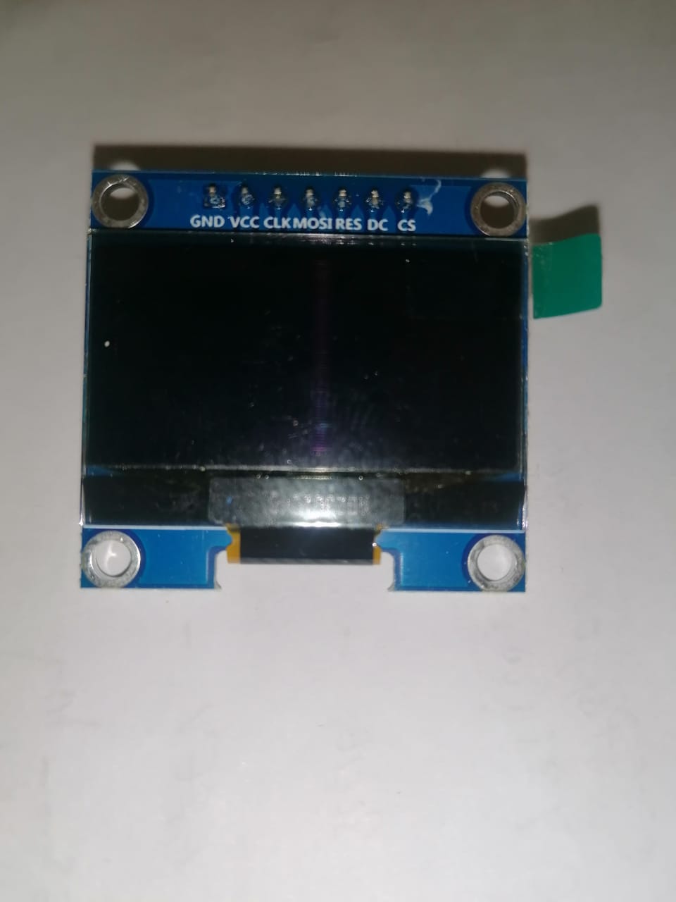
Pins DC & CS to be connected to GND
Pin RES to be connected to VCC
Use pin CLK as SCK (Pin 3 on Pro Micro)
Use MOSI as SDA (Pin 2 on Pro Micro)
Is there anything else I need to do / check. The previous project does have the following in the setup ==> "display.begin(SH1106_SWITCHCAPVCC, 0x3C)" ; using the SSD1306 library
You asked multiple questions in one go...I replied to what is most important as the info I laid out was the online info I located, which you could have agreed to or questioned. I don't appreciate your attitude, this forum should be friendly and open to new users, we don't know everything, else we would not be on here, you included!....but thanks anyway for your assistance...I will find my answers elsewhere or worst case scenario, I'll revert to the 0.96in I2C displays that I used before..
Thank you...I don't think i have tried that but will do. I powered up the Arduino and the display connected as per my initial description....unfortunately the display does not light up at all, so there is definitely something I missed along the way. I will remove the display tomorrow and test another one, failing which, I will revert to the original 0.96in display.