There is more, much more to it than just a switch. Just as a general example.

Merely one basic example of a DC SSR but note how polarity figures into things in this example.
Ron
There is more, much more to it than just a switch. Just as a general example.
Merely one basic example of a DC SSR but note how polarity figures into things in this example.
Ron
Hi,
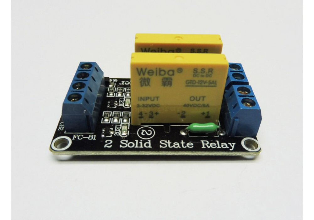
NOTE, OUTPUT TERMINALS, -2 and +1.
The output is polarised, so you have to get the connections correct.
Tom... ![]()
![]()
![]()
![]()
Thanks Ron for taking an interest in this. I see from your diagram there is more to it. However in this case there's no polarity marked and I've tried it both ways anyway. It's a strange one the activation LED on the SSR second channel isn't lit yet the relay is activated which initially mad me think it was faulty, yet when using this channel in isolation, it works fine. This only seems to happen when attempting to use both channels.
Now I've just reconfigured it, ensuring correct polarity. Now the LED CH2 circuit - the activation LED on each channel is working but the LED is constantly lit. As is the fan. Am I missing something?
Yes, Between control voltage + and control voltage - (ground).
Also if you notice on the case the input pins are labeled + and - as well as the output pins.
Ron
OK, thanks. I always connect appropriately if polarity is noted. Will try the resistors but i'm thinking this isn't the issue, as the SSR LEDs are working fine, it's the switching side....
From here, the last sentence:
Your power to the module is 5V, but the switched load uses 12V power. Perhaps test with led and 220R load connected to 5V to see if it switches correctly.
Have tried this - no affect. Even with no switching load, the SSRs still don't function appropriately. Seems like a guessing game at this stage? Does anyone have any definitive knowledge or experience on this matter? Hoping so!
thank you - code appears to work brilliantly and a good example of the Case function too. However the problem appears to be on the switched side of the SSR, not the switching side. The switching side works and flashes appropriately under this sketch but the switched side remains always on.... ![]()
Check page 44 here.
Looks like you need to install a bleeder resistor.

I think the leakage current is keeping the LED on.
Hi,
Does the LED or the Fan stay ON?
Or both?
What is the fan, do you have some specs?
If you completely disconnect the Arduino side from the relay module what happens?
What is written on the side of your SSR?
Part number etc.
Thanks.. Tom.. ![]()
![]()
![]()
![]()
Yes, both stay on
Have attached photo of the SSR
If you completely detach Arduino, makes no difference - SSR appears latched on although activation LED is out
Fan is 12V computer fan 12V 0.12 A so again a low load
Brilliant! thank you. So according to this, the load I've imposed isn't heavy enough so I need to place a 620 Ohm 1 W load in parallel to the actual load/LED/Fan? this is to increase the leakage current?
This sounds right as entirely on the switched side of the relay, might be a while before I can get some resistors but excited to try this
Yes
This provides a path to GND to drain the existing output leakage current. Its connected like a pulldown resistor.
To test a more substantial load ... If you have a 60 watt incandescent light bulb, its typical resistance is 24 ohms, so it would draw about 0.5A when conncected to 12VDC.
thanks again. I only have a few select resistors, am I aiming at a specific resistance across the contacts? obviously the LED is negligible at 20mA + it's 600 Ohm resistor, and the fan is 0.12 A. I have one 600 Ohm, one 1.2 kOhm resistor and more in the 2.2 kOhm range, can you give me an idea of whether these might be ok? I don't want to pop anything
For the 600 ohm resistor, the power calculates to about 1/4 watt, so it should be at minimum 1/2 watt, preferably 1 watt, and connected as suggested here ...
thanks. Are you able to share the power calc/equation? What happens if the power exceeds the resistor's power rating - pop? then I can work out for myself
Power Formulas in DC Circuits
Using No. 3 ... Power (Watts) = (12x12)/600=0.24
Therefore, a 1/4W resistor would likely blow, 1/2W would run hot, 1W is best for a permanent installation.
Hi,
Don't be scared to try the higher value resistor you have there.
Try three 2K2 in parallel. That will give you 733R.
Each resistor will be dissipating (12 x 12 ) / 2200 = 0.06W for each resistor, yours are probably 0.25W.
Tom.. ![]()
![]()
![]()
![]()
I've got a bunch of these at 103 so appears to be 0-10 kOhm, I can dial these down to the required 680 Ohm and I'm guessing from their size they can dissipate the 1W easily.... ?
Hmm - did this on the LED CH2 side in parallel with the load (LED + resistor) - made no difference. Pot set at 680 Ohms. LED still stays lit even though SSR CH2 LED flashes per the sketch, appears the switching side still not deactivating
This is frustrating - the switched sides are just not deactivating when both channels are connected, yet appear to work ok individually. Oops and my pot caught fire ![]()
This 60V 1/2 amp PhotoMOS relay (available in 4-pin dip) is much better suited for your application. Only 1μA leakage.