ST7789 2.8Inch Display with Arduino Nano

I am trying to run ST7789 SPI 2.8Inch TFT display with Arduino Nano but it doesn't just work. I have validated the wiring on the circuit. Saw many tutorials, but it doesn't just work. The display's PCB is below


Below is the configuration of my wiring with Arduino Nano.
#01 GND -> GND
#02 VCC -> VCC (3.3V only!)
#03 SCL -> D13/SCK
#04 SDA -> D11/MOSI
#05 RES -> D8 or any digital
#06 DC -> D7 or any digital

I used the FAST ST7789 Library. Please note that, in total of 3 hours of struggle the hello world example displayed for about half of a second and then flicked away and then no overall output. This only happened between my struggle to display something onto the screen.

I used multiple other Arduino Nanos as well as an Arduino Uno. But it didnt work as well.

Welcome! Three hours is not that long, I have spend days on problems as have many others. You may have a bad display, cannot be sure at this point. Can you post an annotated schematic showing exactly how this is wired, show all power sources, grounds and note any wire over 25cm/10".

I just tried a different diagram that I saw in the this video.

The screen is turning on but its just a white light. I am using the same Fast ST7789 library.

The Schematics are below:
schematics

Moreover, I am using the D10 pin for CS. Code is below:

#define TFT_CS    10
#define TFT_DC    8
#define TFT_RST   9 
#define SCR_WD   240
#define SCR_HT   240   // 320 - to allow access to full 240x320 frame buffer
#include <SPI.h>
#include <Adafruit_GFX.h>
#include <Arduino_ST7789_Fast.h>
//Arduino_ST7789 lcd = Arduino_ST7789(TFT_DC, TFT_RST);
Arduino_ST7789 lcd = Arduino_ST7789(TFT_DC, TFT_RST, TFT_CS);

void setup(void) 
{
  Serial.begin(9600);
  lcd.init(SCR_WD, SCR_HT);
  lcd.fillScreen(BLACK);
  lcd.setCursor(0, 0);
  lcd.setTextColor(WHITE,BLUE);
  lcd.setTextSize(3);
  lcd.println("HELLO world!!!!");
 }

void loop()
{
}

Does your Nano or UNO run at 16MHz?

If not, then the FAST ST7789 authors' site recommends adding:

define COMPATIBILITY_MODE

to your code. See here:

^GitHub - cbm80amiga/Arduino_ST7789_Fast: Fast SPI library for the ST7789 IPS display

Worked with some different wiring. Needed to remove CS pin. FIXED!!!

Here is the code:

#define TFT_DC    8
#define TFT_RST   9 
#define SCR_WD   320
#define SCR_HT   480   // 320 - to allow access to full 240x320 frame buffer
#include <SPI.h>
#include <Adafruit_GFX.h>
#include <Arduino_ST7789_Fast.h>
Arduino_ST7789 lcd = Arduino_ST7789(TFT_DC, TFT_RST);

#include "bitmap.h"

uint16_t colorBar[50];

void setup(void) 
{
  Serial.begin(9600);
  lcd.init(SCR_WD, SCR_HT);
  lcd.fillScreen(BLACK);

  int i,j;
  for(j=0;j<7;j++) 
    for(i=0;i<7;i++)
      lcd.drawImageF(i*34,j*34,32,32,mario);
  delay(4000);

  for(i=0;i<25;i++) {
    colorBar[i]    = RGBto565(i*256/25,0,i*256/25);
    colorBar[i+25] = RGBto565((24-i)*255/25,0,(24-i)*255/25);
  }
  for(i=0;i<240;i++) {
    lcd.drawImage(i,0,1,50,colorBar);
    lcd.drawImage(i,240-50,1,50,colorBar);
  }
  for(i=50;i<240-50;i++) {
    lcd.drawImage(0,i,50,1,colorBar);
    lcd.drawImage(240-50,i,50,1,colorBar);
  }
  delay(4000);
}

void loop()
{
  lcd.drawImageF(random(0,240-32),random(0,240-32),32,32,mario);
}

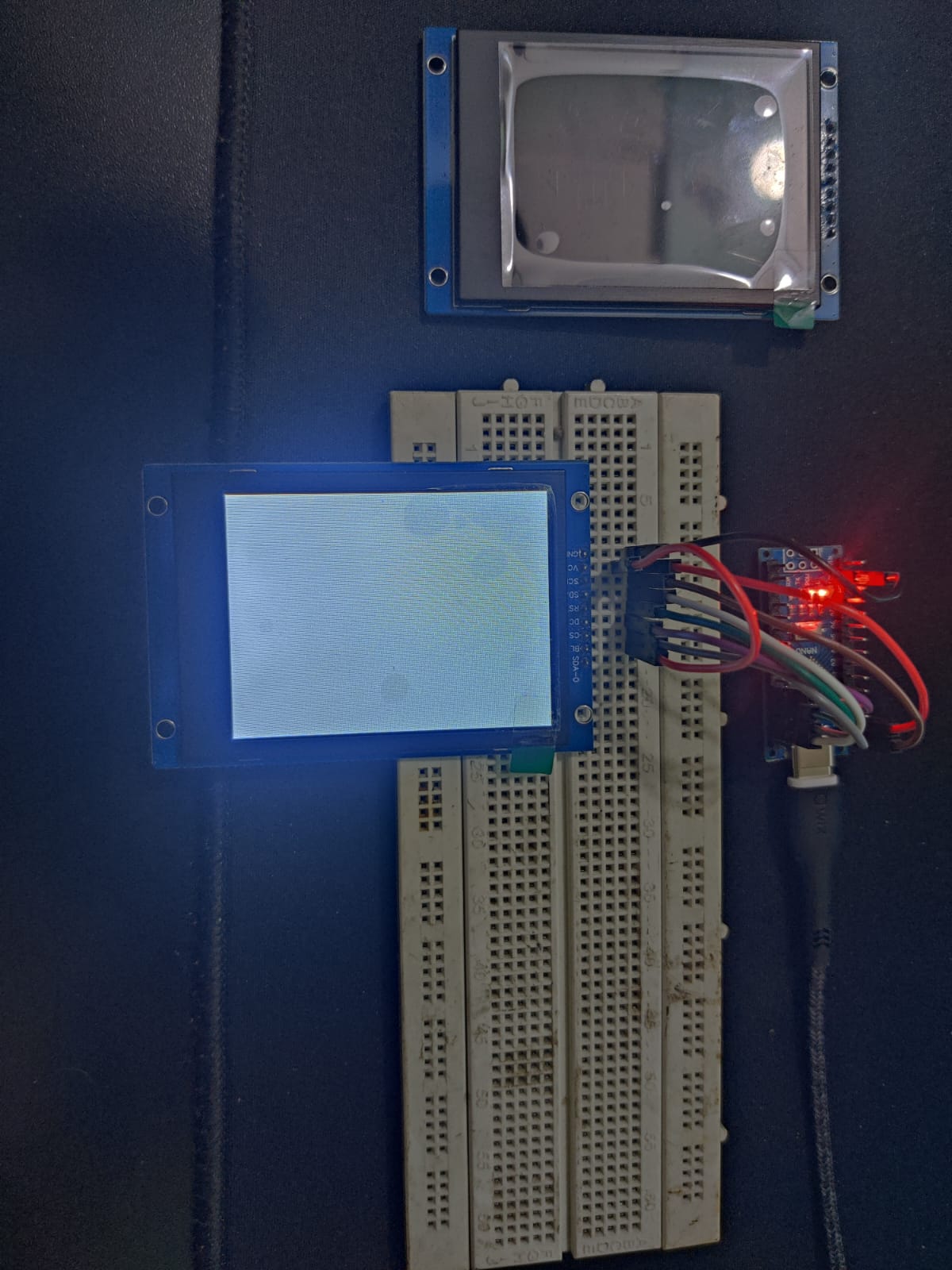
Just to let you know, so you can avoid similar problems in future: Nano is designed to be plugged into the breadboard. You soldered the PCB header pins incorrectly. They should be underneath the Nano.

Yes. Thank you for letting me know. I actually needed to solder it in this way as I have to place it in a plastic body of a product that I am making.

This topic was automatically closed 180 days after the last reply. New replies are no longer allowed.