mauried:
Can you provide more info on the crystal?
In particular, is it cut for series or parallel mode , and is it a fundamental or overtone crystal.
Thats a very odd circuit for a crystal oscillator.
A google search doesn't turn up anything on the particular 3mHz crystal I'm using. It's marked "D.M. 3.000 LY0330". Most of the other crystals I have on hand do not have part numbers on them. That is the disadvantage to getting cheap parts off Fleebay. As for the circuit being odd, I'll have to agree with Paul, it's not really an odd circuit. Circuits like these were fairly common 20 years ago in many 8-bit systems. Although many times they would also use a divider of one kind or another to achieve a lower lower frequency of oscillation. Take the TI-99/4a as an example, it used a 12mHz crystal, which was then divided by four to achieve 3mhz. Also, you have to remember, back then many processors (possibly all?) didn't have two XTAL pins. They had a single clock pin. So the method of providing a clock signal was similar to the various examples mentioned above. Like the PDF I linked to above states, "relatively little information has appeared on circuitry for crystals and engineers often view(ed) crystal circuitry as a black art, best left to a few skilled practitioners". Today, all the additional circuitry is located within the MCU.
@Tom, I will definitely read those two. I appreciate the links. I did the initial prototyping on breadboard just to confirm the circuit was doing 'something'. Once that was confirmed I designed a quick board in eagle and tried them out with a few different values of caps and resistors trying to fine tune. I don't know what it is about perfboard or strip board, but I tend to get about half way through and loose track of where I'm at and what I missed. So if it isn't a large circuit, and I have some appropriate pieces of scrap PCB laying around, I'll just etch a small circuit.
@Paul, So can I assume that, since this particular crystal seems to oscillate with two inverters versus three, these crystals I have are cut for series oscillation, not parallel?
Paul__B:
That would seem to be rather retrograde. The difference between HC and HCT is that HC is symmetrical in contrast to HCT and LS. If one is trying different, more primitive logic types, it simply means one has no idea what one is doing.  I would be more inclined to "lose" the 120 pF capacitor which appears to be peculiarly unique to that particular web-page!
Ha, I'm not sure which of us that you're referring to in the sentence before the smiley, but the humor definitely made me smile on this rainy day. I tend to think that most of the time, when one resorts to the forums, it's because they don't know what they're doing, and are looking to bath in the pool of knowledge of other, more knowledgeable, individuals.
But as for older technologies, if I'm not mistaken, LS predates HC and HCT. Both examples of the circuit I'm using show LS logic. However, I don't have any on hand. So I figured I might be able to get away with HC. But I'll acknowledge that it could be the source of the duty cycle issue. If LS has a lower threshold of what it sees as a HIGH than the HC does, the problem with duty cycle could be that the HC is seeing the HIGH slower than the LS would. Or to put it another way, because of the variation of the oscillation, the 74HC04 is taking longer to register that there is a HIGH signal, whereas the 74LS04 in the example is able to switch on at a lower voltage. And what you mentioned about the 120pf cap holds water, if I place one in the circuit oscillation stops or becomes very erratic.
@Mark, that is very interesting. I generally though of all crystal circuits as analog, which are then passed through a digital gate to convert the signal to a square. My understanding is they essentially all start off as a sine. And the gates are there to do that conversion. I think I should probably do a little more research on overtones, I really don't know much about them. Most of the material I've read mentions them in passing, but didn't delve too deeply into them.
JohnLincoln:
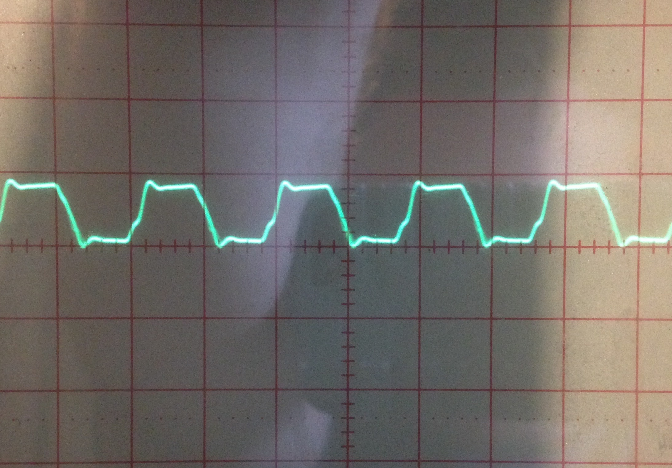
I think that your perceived 'problem', is due to the limitations of your test equipment.
Your logic analyser, is sampling a waveform that is roughly sinusoidal, and converting it to a square/rectangular waveform.
The sampling frequency of 24MHz is only 8 times the oscillator frequency.
If the waveform that you are viewing is high for 4 of the logic analyser's clock periods, and then low for 4 clock periods, it will indicate a duty cycle of 50%.
However if the logic analyser 'sees' the signal as being high for 5 clock cycles and low for 3 clock cycles, it will indicate 62.5% duty cycle.
For an input frequency of 3MHz, your analyser can only indicate certain quantised values for the duty cycle.
For example if you put in a rectangular pulse with a duty cycle of 51%, because that is greater than 50%, it would indicate the next higher value that it can, i.e. 62.5%.
John, now THAT makes sense. It's a cheap analyzer. I think it was $10 or so. And it obviously has it's limitations. Sticking this on better equipment would be more insightful. However, being a hobbiest, it's not really in the budget. At least not yet. I've got a buddy who is an aviation technician. I need to go drink a few cold ones with him, so I might see if while we're doing so if he'll kindly test it for me. Because if what you're suggesting is true, it very well might be a very consistent clock.