Hey community!
I want to build/solder a setup where I can use the following components
- RCW-0001 ultrasonic distant sensor
- D1 Mini ESP8266
- Wemos Battery Shield
- a little battery which fits the battery shield
I also have a mini breadboard like this, since I guess the sensor has to be connected with jumperwires:

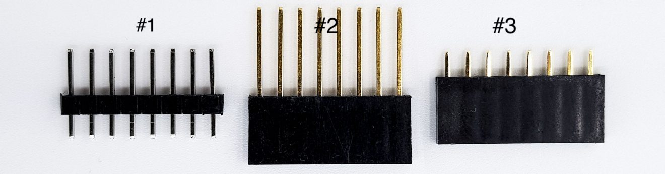
Since Wemos always adds three different kinds of addon-pins to their packages (don't know how they are exactly called but I guess #1 are male header pins, #2 are long female headers and #3 are short female headers?!) I wonder how I need to combine and solder those in a correct way.
Because I then need to connect the jumperwires from the sensor to a female pin, I think such long female pins (#2) need to be the top part in the stacking. After that my guess is the following (left side is schematic, right side is just stacked but not soldered):

Regarding the soldering I then need to solder every connection where one of those pins is touching the D1 mini and/or the battery shield, right?
But there is the point where I am stuck since the lowest long female headers won't fit into the breadboard. What possibilty do I miss?
(The final product should be as small as possible...)
Does this even sound like a functioning project?
Thank you all and have nice day!

