Now we'll be adding the USB to Serial breakout board to our Arduino breadboard circuit. If you haven't added male headers to your breakout board, you will need to do it now.
Connect the VCCIO of the breakout board to power and the GND to ground.
Does 'Serial' mean RS232?
Assuming I have a USB to RS232 converter with a small circuit board embedded in the USB plug and free RS232 connectors at the other end. When you plug it in windows recognizes it as an additional com port, compared to if you plug the arduino in via the usb cable provided with it then windows recognizes it as an 'arduino'.
If I connect up the free RS232 connectors to the arduino on my breadboard, as described in the above web site, how do you get the arduino development environment to talk to it?
Because windows only recognizes the USB ro RS232 converter as a com port but the arduino development environment
No, it is not RS-232, it is serial TTL levels and the opposite polarity to RS-232. Do be careful!
You need to use one of the readily available "USB to TTL" adapters. You could use a USB to RS-232 cable but you would then require an RS-232 to serial adapter to invert the levels.
Paul__B:
No, it is not RS-232, it is serial TTL levels and the opposite polarity to RS-232. Do be careful!
You need to use one of the readily available "USB to TTL" adapters. You could use a USB to RS-232 cable but you would then require an RS-232 to serial adapter to invert the levels.
It is rather confusing on ebay because the chinese sellers seem to have rather confusing descriptions for their items themselves.
boylesg:
It is rather confusing on eBay because the Chinese sellers seem to have rather confusing descriptions for their items themselves.
Yeah, well, they're Chinese, aren't they? XD
boylesg:
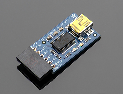
I assume one of these would be appropriate?
Looks good - a faithful representation of the FTDI module. Note that it correctly specifies "DTR" on the sixth pin, the one that goes to the 0.1µF capacitor in series which goes to the Reset pin on the breadboard along with the 10k pull-up (and no other capacitors).
The "bodgie" boards have a pin marked "RST" which tells you they are wired wrongly and need to be modified to be used for this purpose.
But there still seems a long way to go with the plethora of expansion boards etc available for them.
for your workbench and project design activities, I always recommend having one "true" Arduino (an UNO is great). For project builds from designs that you know will work, you can deviate to less-expensive, imported materials. Not having known working or stable components during design and test will simply drive you (and those of us in the forum that attempt to help you) more crazy than we currently are!
This little guy will set you back the cost of one 10" pizza:
OR
And this under $10 unit is a fully supported and licensed unit:
So, for $25 U.S. you can have a fully supported test and programming environment. This is nearly equivalent to the UNO but the UNO will also allow you to use shields to extend the base board. It is a matter of preference since the Sparkfun Pro Mini can very nicely be inserted into the larger solderless prototyping boards.
But there still seems a long way to go with the plethora of expansion boards etc available for them.
for your workbench and project design activities, I always recommend having one "true" Arduino (an UNO is great). For project builds from designs that you know will work, you can deviate to less-expensive, imported materials. Not having known working or stable components during design and test will simply drive you (and those of us in the forum that attempt to help you) more crazy than we currently are!
So, for $25 U.S. you can have a fully supported test and programming environment. This is nearly equivalent to the UNO but the UNO will also allow you to use shields to extend the base board. It is a matter of preference since the Sparkfun Pro Mini can very nicely be inserted into the larger solderless prototyping boards.
Paul__B:
No, it is not RS-232, it is serial TTL levels and the opposite polarity to RS-232. Do be careful!
You need to use one of the readily available "USB to TTL" adapters. You could use a USB to RS-232 cable but you would then require an RS-232 to serial adapter to invert the levels.
Is the only difference between RS232 and FTDI the polarity of the logic levels?
For example, could you put the RS232 Tx and Rx through inverting amplifiers, with perhaps a 5V zener diode on the output, and then connect them to the arduino TX and Rx pins?
boylesg:
Is the only difference between RS232 and FTDI the polarity of the logic levels?
And of course, the voltages.
boylesg:
For example, could you put the RS232 Tx and Rx through inverting amplifiers, with perhaps a 5V Zener diode on the output, and then connect them to the Arduino TX and Rx pins?
That's pretty much exactly what the MAX232 (or variant thereof) in the RS232 to TTL converter boards and countless previous RS232 interfaces powered by 5V, is, or does.
The add says RS232 but it can't possibly be standard RS232 with 12V logic levels. USB only has a 5V power supply.
At any rate passing Tx and Rx from the above cable through inverting unity gain opamps, and then into Tx and Rx of my Atmega chip, doesn't seem to work.
Oh, but that is funny! Here we are running round in circles and you already have the precisely correct cable for the job. As I believe you hinted in your first post here.
boylesg:
The ad says RS232 but it can't possibly be standard RS232 with 12V logic levels. USB only has a 5V power supply.
Well, it isn't RS232 for a start because it has the wrong voltages and the wrong polarity. So much for descriptions on eBay.
As it happens, this has nothing to do with whether it is USB or not, because the MAX232 chip that can be (and is) used in an actual USB to RS-232 cable uses charge pumps to firstly double the 5V to 10V, then invert that to -10V in order to drive +- 10V levels sufficient to approximate the real RS-232 standard.
However that may be, that is the cable you use to program the Arduino (or breadboard version thereof) through the USB port using the IDE. The voltages and polarity are absolutely correct, no need for inverters, converters or anything, you just connect it to the Arduino. It does require three things: Windoze must recognise the device - the correct driver must be loaded and you select the port this makes available in the "Tools => Serial Port" option in the IDE; you need to figure out which way Tx and Rx must connect (they generally have to be crossed between the two devices), and since that cable provides no automatic reset, you must briefly hit the reset button as soon as you see the "Binary sketch size: xxxx bytes (of a 30720 byte maximum)" message in the IDE - that sometimes takes some practice.
Well there you go!
Ebay and the chinese sellers are great but it would be even better if they accurately knew the technicalities of the components they sell!
What is with the extra connectors at the end? Just a different manufacture and product that does the same job as mine?
Come to think of it I was reading about that automatic vs manual reset thing some where along the line.
The boot loader is responsible for loading the sketch and you need it to be running when you try to upload.
Except that it only runs once when you power on or reset the arduino. Correct?
The boot loader is responsible for loading the sketch and you need it to be running when you try to upload.
Except that it only runs once when you power on or reset the arduino. Correct?
Yes.
There is a small window of time after the ArduinoGUI instructs the serial port (physical serial or virtual serial over USB) which causes the reset to be pulsed. The timing of this upload window is set inside the bootloader.
Serial USB cables are designed for a variety of uses and some have only 5V and some have 5V and 3.3V and some have DTR and some do not. And, as you found out, eBay description are not always correct. I recently ordered a GPS receiver module from an eBay dealer that also sells adult toys... one simply takes a chance that the item received works and that a datasheet can be located for the chipset. Fortunately, ebay makes it easy for these dealers to post high resolution images. However, some images are not what you actually receive. For those uncomfortable with such shenanigans, avoid eBay and go to Mouser, Sparkfun, Adafruit, and others who guarantee what they sell.
It was not all that long ago (2009) when the auto-reset feature was introduced.
Rather then requiring a physical press of the reset button before an upload, the Arduino Duemilanove is designed in a way that allows it to be reset by software running on a connected computer. One of the hardware flow control lines (DTR) of the FT232RL is connected to the reset line of the ATmega168 or ATmega328 via a 100 nanofarad capacitor.
I actually got those cables and HC06 modules from, I gather, an ebay arduino dealer in the states.
His ebay store was a specific electronics/arduino one and he obviously knew what he was talking about because he advised me correctly as to what cables and bluetooth modules I need to connect an arduino wirelessly.
Sadly I think he still had that incorrect RS232 term in his product description for the cable.
I tried connecting the atmega chip serial lines to those of the bluetooth module rather than the cable directly.
But that still doesn't seem to work, although I have successfully connected an arduino to Teraterm wirelessly using those bluetooth modules.