Hello everyone,
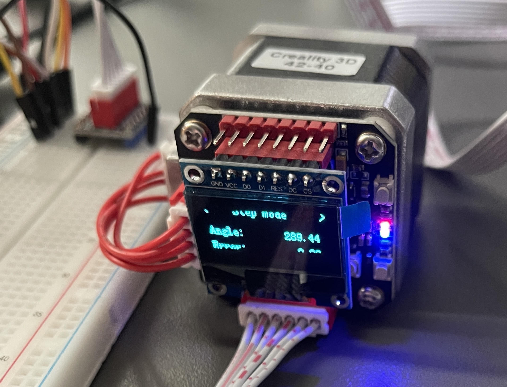
I'm working on my first project where I have to move a stepper motor using a closed loop driver board (Bigtreetech S42C) . I put everything together and uploaded the code but it doesn't move. I think I wired something wrong. The red and black wire of the left side of the breadboard are connected to a 12V power supply. Also are the leds on the driver board supposed to bling red and blue?

Schematics and datasheet, please.
Help us to help you. For beeing helpful you must provide more information.
What code did you upload?
Post this code as a code-section like shown in this tutorial
How did you upload this code to what exact type of microcontroller?
From your pictures nobody can conclude what is connected to what.
You will have to draw a schematic how you have connected the wires.
At least describe each wire as
starts on microcontroller-IO-pin named "...." is connected to IO-pin named "...." at the steppermotordriver.
best regards Stefan
Thanks. Please read the reply #2 again and post the rest of the request.
```cpp
int stepPin = 8;
int dirPin  = 9;
int  enPin  = 10;

int numstep = 1030;
unsigned long ldelay = 100;
unsigned long mDelay = 500;

void setup() {
  // put your setup code here, to run once:

     pinMode(stepPin,OUTPUT);

     pinMode(dirPin,OUTPUT);

     pinMode(enPin , OUTPUT);

     digitalWrite(dirPin, HIGH);
     digitalWrite( enPin , LOW);
}

void loop() {
  // put your main code here, to run repeatedly:

  for(int x = 0; x < numstep; x++) {

           digitalWrite(stepPin,HIGH);

           delayMicroseconds(ldelay);

           digitalWrite(stepPin,LOW);

           delayMicroseconds(ldelay);

        }

    delay(mDelay);
    digitalWrite(dirPin, LOW);

    for(int x = 0; x < numstep; x++) {

           digitalWrite(stepPin,HIGH);

           delayMicroseconds(ldelay);

           digitalWrite(stepPin,LOW);

           delayMicroseconds(ldelay);

        }

    delay(mDelay);
    digitalWrite(dirPin, HIGH);

}
Well I don't have a software to draw a schematic.
Pins of the driver are:


VM     Connected to 12V Power supply
GND  Connected to GND Power supply
5V      5V Pin of Arduino
GND  GND of Arduino
EN      IO10
STP     IO8
DIR     IO9
other EN to GND Power Supply


The motor is locked in Place but doesnt movedrawing free hand is sufficient.
If you measure for conductance between GND of the arduino on the GND of your 12V power-supply is there conductance?
What does the datasheet say about how to connect the EN-inputs?
What does the datasheet say about if the EN-input is
LOW-active
or
HIGH-active?
Your delays are extremely short 100/300 microseconds
Do a test with 10000/30000 microseconds
and with
1000/3000 microseconds
best regards Stefan
I just measured and changed the delay. There isn't conductance between GND of the arduino on the GND of your 12V power-supply. Also thats the problem. I dont know what exact driver that is. Except for the board thats mounted on the motor (Bigtreetech S42C) there isn't a paper that came with it. I think its a version of the TMC 2209 Idk. I am still kind of new to this.
Thats the link where I got this:
Amazon often does not provide detailed datasheets.
This is a reason to not buy such things at amazon
Did you read and follow the instructions given on the amazon-page?
Quoting:
【NOTES】 Only suitable for motherboards with socket stepper driver installation. 0.9-inch OLED screen, the motor current and subdivision can be modified by buttons, and displayed on the OLED, the operation is simple and convenient; in the absence of OLED, you can use the serial port to connect to the computer, and use the serial communication protocol for parameter adjustment and query S42C V1.1 Closed Loop Driver Control Board Specification: Maximum speed: 2000RPM Main control chip: STM32G031G8U6, 32-bit ARM Cortex-MO+, clocked at 64MHz 【ATTENTION】 1 、When inserting the adapter board, please pay attention to the direction of the adapter board. Notice the motor and the loop chain wiring sequence! 2、For the first time, the closed-loop driver board must be connected to the motherboard with firmware, and then the encoder shall be calibrated. The calibration time will take 1-2 minutes 3、Check if the driver is installed when connecting to the computer with the serial port. 4、When the data displayed on the display or serial port is abnormal, please remove the closed-loop driver board and check if the magnet on the motor shaft is in the center position. If not, please return it to the center for recalibration. 5 、After completing the calibration, do not set it immediately after power-on. Please wait for the initialization to complete (1-2s) before setting the parameters. 6、Please do not manually turn the motor after power on. 7、The distance between the magnet at the center of the motor shaft and the core encoder should be greater than 2mm. 8 、Full stability of machine structure must be guaranteed If you have any questions, please give us a chance to understand, feel free to contact us to solve it for you,thank you
ok.. so I won't be able to run that directly off an arduino?
Do I need a controller expansion board like in that video?
Edit: I see you cant share a youtube video here. The title:" Easy way !! Arduino closed loop stepper motor control"
From what do you conclude that?
It should be possible to run it directly from a microcontroller.
but all details must match?
hence these questions that you haven't answered yet
not doing these steps and not answering the questions does not help
way too unprecise
post the url as a code-section
If you have reached trust-level 1 you will be able to post video-links and pictures
Did you do the steps as described in this video?
 - Tests & Results")
If you ever plan to use a simpler setup, you can consider using an L298 and Nema17 stepper motor. Though this will be a quite low level setup compared to what you are using now.
I explicitly say: don't use a L298!
These are so crappy old fashion chips. Inefficient and you have to take care of a lot more details than with using a stepper-driver like a A4988, DRV8825
or
what I recommend a TMC2209
Ok, sorry I misunderstood. I don't have the model of the driver and no paper came with it so I dont have the datasheet. Only thing I have is a link to a github page of the board..
From what I understand about the TMC 2209 and I don't even know if it is a version of it, but it would be LOW-active. Only hint I have is a number on the backside of the driver "22 12." . But I couldn't find anything from googling it. Delay is now set to 10000/30000.
Fot the video. I don't have a 3d printer right now that I can test it on. And the board doesn't have a usb port either:/
No it is surely not a TMC2209. It would look different.
You should test if it is low-active or high-active by
modifying the code to with EN switched to HIGH
and
then
with EN switched to LOW
Alright, I did that now. If its LOW its locked. If its HIGH you can turn the shaft by hand. So LOW is active. The problem is it wont move
This topic was automatically closed 180 days after the last reply. New replies are no longer allowed.