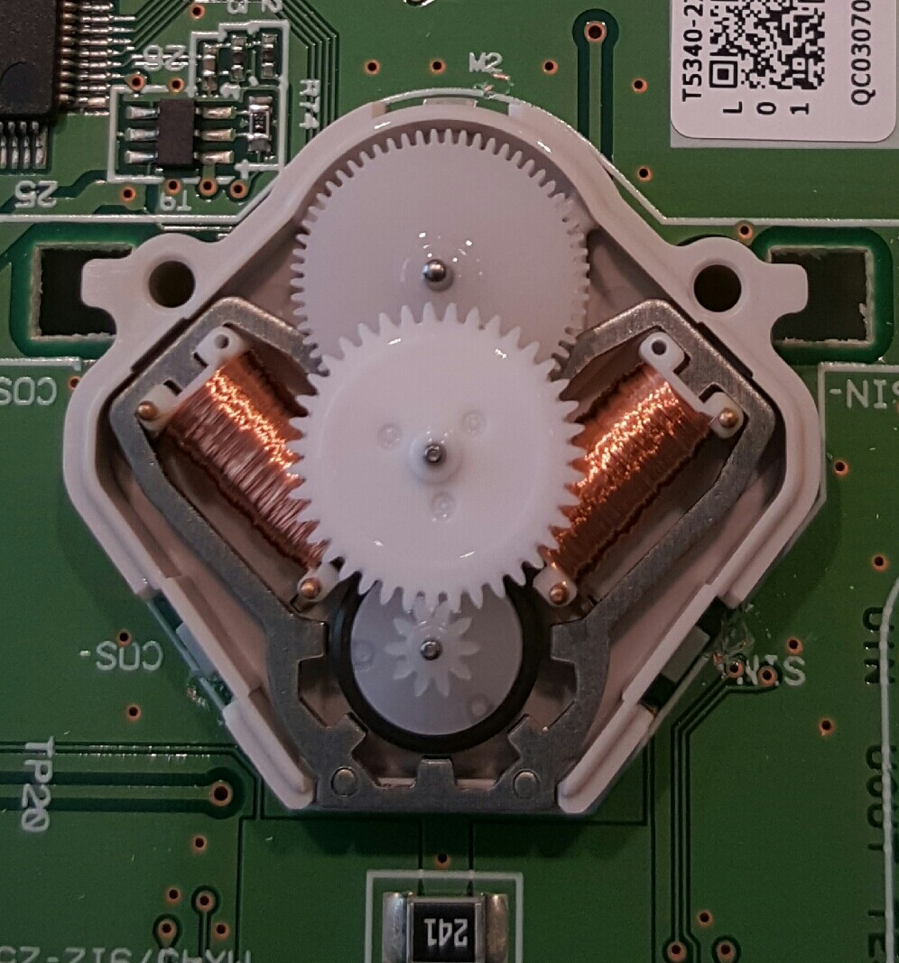
What is the best way to drive this particular stepper. It will be used to drive an automotive gauge needle.
Thanks in advance.
What is the best way to drive this particular stepper. It will be used to drive an automotive gauge needle.
Thanks in advance.
It appears to have two coils, in which case it would be just like any other bipolar stepper motor.
You need a dual H-bridge stepper driver. Just about any would work.
Hi,
Probably the same as these.
measure the coil resistance, the if the same, then check this site for driver and possibly code.
Tom.... ![]()
http://arduino-info.wikispaces.com/SmallSteppers
you can use the uln2003 a cheap driver if yours works on 5 v
jremington:
It appears to have two coils, in which case it would be just like any other bipolar stepper motor.You need a dual H-bridge stepper driver. Just about any would work.
It does have 2 coils but the stators are all one continuous piece which has me scratching my head on the manner in which this system operates.
Thanks
Magnetic fields add linearly, as long as the magnetic circuit is not saturated.
Stators are generally all one piece: 
manav_sethi:
http://arduino-info.wikispaces.com/SmallSteppers
you can use the uln2003 a cheap driver if yours works on 5 v
No you can't. This is a 4 wire bipolar motor, not a 5 wire unipolar motor.
I have the TB6612FNG driver from pololu. But according to an article for the switec motor (uses switec library). This can be driven off of the Arduino directly as the current draw is extremely low.
I know that some on here will disagree.
It is not the typical Switec gauge motor, but it is similar in appearance. Here is what the innards of the Switec look like: DIY: stuck instrument motors | E46 Fanatics Forum
If the coil resistance is greater than about 200 Ohms, you can drive it directly with four output pins. Flyback diodes (8 of them) are required.
The requirement for 8 diodes means it may actually be easier to drive it from a stepper driver board! I
have done this in the past for a tiny tiny stepper motor, and used a surface-mount 8 diode array called
a QSBT40 http://www.diodes.com/_files/datasheets/ds30195.pdf
a surface-mount 8 diode array
An equivalent as "hole through" alternative would be:
Nice find, but obsolete I think
Nice find, but obsolete I think
Why that? I am old school and don't like to solder SMDs; my eyes plus glasses don't comply to SMDs ![]()
Anything thru-hole (unless high power) is obsolete really these days...
I suggest considering the acquisition of a cheap toaster oven and a syringe of solder paste, and these: Vision Care Products for sale | eBay
For complex PCBs get a stencil made (I laser cut mine from paper for one-off use!)
Then its relatively easy to produce this sort of quality:
[ for completeness, its an ATmega168 and a DRV8711 stepper controller with 4 dual MOSFETs, capable of driving 5A bipolar steppers ]
@MarkT:
Do you have a suggestion for the toaster oven and its parameters (heat, time to bake the pcb et.) then I would give it a try. And: where do you buy the pcb's?
But, keep in mind, my eyes are 62+ years old and I don't like to stress them too much as I want to see some years more ![]()
Cheapest you can get, I got one with elements top and bottom, and I moved the bottom
one to the top for more even heating. If you have a multimeter with a thermocouple you can
figure out roughly what the temperature settings mean.
To cook a board, set to soak temperature for about 3 minutes, then full power until the solder paste reflows
(need a good light source to see the shiny beads of molten solder). Count to 5, power down, open
door and pull tray gently out to let cool.
Some people do a conversion adding a thermocouple and SSR under Arduino control.
Thanks,
will give it a try and see if this is something for me in the future.
My "problem" is, that I still have thousands of TH-devices (45 years old collected stuff - but still working, all the transistors, resistors, diodes and not dries out caps ...)
Do the SMD parts first, then add the thru hole.
4 element toaster oven works best, ramps the temperature up to the flux activation stage (~100-125C for 90 seconds), then a 2nd ramp up to the reflow stage (~190-195C for 90 seconds, do not exceed 205C), then heat off and cool down, open door slowly until temp drops below 183C, then can open more fully to finish cooling off. 2 and 3 element heated ovens can take too long.
I also have a lot of thru hole parts, problem is many Rs & Cs are good values for analog work but not digital, and many logic chips have been replaced by doing something in software, plus the old fast stuff runs very hot/draws a lot of current compared to a CMOS microcontroller and some CMOS buffers/shift registers.
Sometimes you need just the right chip tho, and the old stuff comes in handy.
Thank you @CrossRoads,
that was helpful in addition to @MarkT's recommendation. So I will give it a try and I have a challenging new Arduino based project as well to control the heating.
Made already some little experiences with SMD based kits - soldered them with a hot air gun (but you can imagine how tricky that is, when you want to solder 20 pieces at the same time using hot air ...)