I am using a drv8825 with an arduino to control a nema 17 stepper motor. It works fine, until the motor abruptly stops for half a second or so, to then keep spinning like normal. This happens about every third second, making the motor unusable. I have tried switching the motor and switching the drv8825, but the problem persists.
I connected it to the arduino following a schematic found here, and I have double checked it fifty times.
I tried to use both pyfirmata and the arduino software for controlling the motor, but the same problem occured both times. I'll post the code for both the attempts bellow.
I have set the current limit thingy correctly, so the problem is not that the motor isn't getting enough power.
The power supply I'm using provides 15V at 6A DC.
Any help would be very appreciated since I haven't found anyone else who has ran into the same problem.
Here is the arduino code I used (taken directly from a video):
#define stepPin 10
#define dirPin 11

void setup() {
  // Sets the two pins as Outputs
  pinMode(stepPin,OUTPUT);
  pinMode(dirPin,OUTPUT);
}
void loop() {
  digitalWrite(dirPin,HIGH); // Enables the motor to move in a particular direction
  // Makes 200 pulses for making one full cycle rotation
  for(int x = 0; x < 200; x++) {
    digitalWrite(stepPin,HIGH);
    delayMicroseconds(1000);    // by changing this time delay between the steps we can change the rotation speed
    digitalWrite(stepPin,LOW);
    delayMicroseconds(1000);
  }
  delay(1000); // One second delay

  digitalWrite(dirPin,LOW); //Changes the rotations direction
  // Makes 400 pulses for making two full cycle rotation
  for(int x = 0; x < 200; x++) {
    digitalWrite(stepPin,HIGH);
    delayMicroseconds(1000);
    digitalWrite(stepPin,LOW);
    delayMicroseconds(1000);
  }
  delay(1000);
}
Here is the python code:
import pyfirmata
from time import sleep

board = pyfirmata.Arduino('COM3')

step = board.get_pin('d:10:o')
dr = board.get_pin('d:11:o')

while True:
    dr.write(1)
    input('')
    for i in range(200):
        step.write(1)
        sleep(0.05)
        step.write(0)
        sleep(0.05)

    dr.write(0)
    for i in range(200):
        step.write(1)
        sleep(0.05)
        step.write(0)
        sleep(0.05)
Do you have the heatsinks fitted securely ?
Do you have pictures of your layout or a schematic or both even.
Not sure about the steps either 200 is the default provided no micro stepping is involved.
What happens if you lower the Delay or swap it to microseconds ?
Not familiar with Python enough to help in that respect.
Hi,
Can we please have a circuit diagram?
An image of a hand drawn schematic will be fine, include ALL power supplies, component names and pin labels.
Your circuit diagram, reverse engineer your project.
Do you have a DMM?
Nema 17 tells us nothing of the steppers electrical characteristics.
Please post a link to data/specs of the stepper motor.
Thanks.. Tom.. 


You use several 3 1 second delay per loop turn in the code...
Link to motor (dont judge me I'm poor): https://www.aliexpress.com/item/1005001303445983.html?spm=a2g0o.order_list.order_list_main.35.21ef1802nGU66y
The best circuit diagram I could make, not sure this is what you asked for.
No capacitor between vmot and ground.
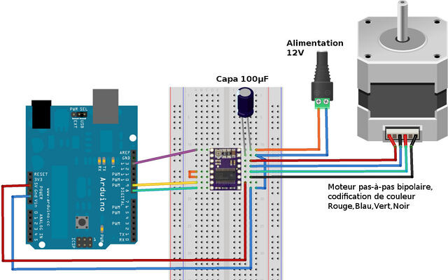
yes I know its not your picture but the arrangement applies.
BTW I do not support the use of breadboard for motor usage.
Look for a way to replace the delay(s) in your sketch so that the processor does not stop while waiting for the time to elapse, unless of course the delay is absolutely necessary for functionality.
See BlinkWithoutDelay example in the Arduino IDE > Examples > Digital section.
Is that capacitor necessary for proper function or just there to stop voltage spikes? I do not have any capacitors, and if they are just there to stop the drv8825 from dying I'm willing to take my chances.
Is this a problem in the python code aswell?
You will probably need a spare driver if you are going to take chances like that.
Pretty much all the examples I can find have the capacitor !
Consider scavenging one from some old electronics.
Those that don't have the capacitor are living in a dangerous world of chance and fate.
I didn't read the python code as I have low experience with it.
I am driving multiple steppers on DIY CNC, so the following items need attention:
Power (quantity and quality), signalling (quantity and quality) and code.
I'd be interested to see the signals coming out of the arduino to the motor driver bracketing the abrupt stops. You could put LEDs on the signal lines, which will flash to indicate change of state. Hardware debugging 
1 Like
I see. I will do my best at finding one to protect my little guy.
Is the capacitor's absence a potential cause for my issue though?
Most likely you have the current limit set too high on the driver, so it overheats and shuts down. Set it for 1.5 Amperes or less.
For a homebrew CNC seriously consider using the CNC shield.
Not only will it make life easier it comes with the required capacitors etc.
They are laid out to take best advantage of a UNO and I use them here for a CNC Laser using GRBL

I have set it to 1.3 amps. I used Vref * 2 to get that number, which is the formula I found everywhere I looked. Is it possible that the issue is that the current limit is too low and not too high?
Nice board but I upgraded to MACH-4 and dedicated drives a while ago.
I found the arduino approach limiting factor during FAST multi-axis simultaneous control. Good learning curve tho.
For a given current limit setting, the Vref value depends on the value of the current sense resistor, which varies from PCB manufacturer to manufacturer.

What is the value of that resistor, on the driver boards you have?
There are alternative 32 bit ESP based boards using a much upgraded GRBL.
I have a MACH 3 based machine here and will be replacing the BOB with something better.
Caps usually help in times of transient events, i.e. switching on.
They supply a local reservoir of available current to cover such events.
If you are connecting just the boards as shown, and the motor shaft is not under load (free running), your wires are connected properly and of reasonable csa and length, it's a bit difficult to diagnose remotely. Connect a resistor and LED as shown, run your sketch as before and observe the LED and motor behaviour.
1 Like

