Stepper motor rotates slower and erratically under load

I am using an Arduino Zero, along with a TB6600 to drive a NEMA 17 stepper motor, to drive a pulley / belt. When I run the code below, without anything attached to the pulley, there is some slight pausing / reversing. However when I attach a belt to the pulley, the motor rotates somewhat slower, and a bit more erratically (more pausing / reversing).

Here's a video to demonstrate:

If it's not clear from the video, this stuttering seems to result in about a 30% slowdown in rotation. (1.09 seconds per revolution under load compared to 0.69 (nice) seconds per revolution when not under load).

Here is the code I am using:

// Define stepper motor connections:
#define dirPin 2
#define stepPin 5
void setup() {
  // Declare pins as output:
  pinMode(stepPin, OUTPUT);
  pinMode(dirPin, OUTPUT);
  // Set the spinning direction CW/CCW:
  digitalWrite(dirPin, HIGH);
}
void loop() {
  // These four lines result in 1 step:
  digitalWrite(stepPin, HIGH);
  delayMicroseconds(483);
  digitalWrite(stepPin, LOW);
  delayMicroseconds(483);
}

This is lightly modified sample code which I've changed the number of microseconds from 500. Testing with a loose binary search between 200 - 800, this was the value that seems to produce the most smooth operation, other values (even 10-20 less) would decrease total revolution speed by 30% or more just due to erratic direction changing.

Here are my questions:
1. Does anyone know why this direction changing is happening? Are there changes in design that you would suggest to deliver power more efficiently? (Next step in the project is to attack the pulley to curtains, so that the arduino can close / open the curtains.)

2. Do these values for delay make sense? Is there a more straightforward way to calculate what the timing should be? I have only ever kept the delays after high and low as the same value, should those be differentiated? A quick google search of "delayMicroseconds(483);" shows a number of results (in Chinese) which happen to use that as a value as well, which may not be a coincidence.

A copy of the spec sheet for the specific NEMA 17 stepper I'm using is here: https://www.mybotonline.com/download/17HS15-1704S.pdf

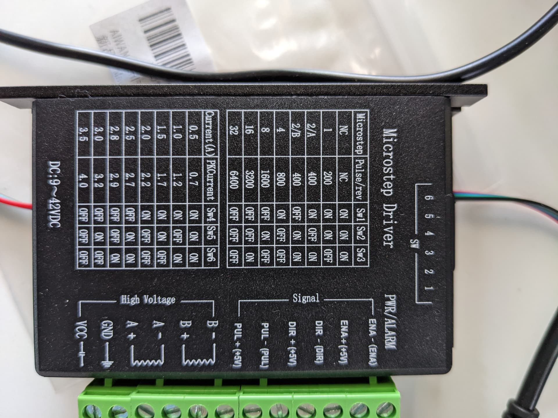
Additional requested info:
Pictures of the TB6600 switch diagram, and my current settings should be attached. I have the "microstep" "pulse/rev" set to 4 / 800 respectively, and the current set to 1.5A. (1.5A I believe I pulled from the datasheet of the motor, 4/800 was chosen just via trial and error with many settings to get the motor to spin at all, as otherwise it would just vibrate, although I haven't done exhaustive testing between different pulse settings and different timings).


How do you power the stepper and how did you set the current limit?

If you use the AccelStepper library you can adjust the max. speed and acceleration which both can cause erratic stepper behaviour. Your code allows to restrict the max. speed but does not handle acceleration.

Attach the load and find out the maximum possible speed and acceleration. Then reduce both to safe values.

Posting a schematic showing all connections and the driver hardware complete with links to the technical information will help a lot.

Sounds like you are trying to jump from standstill to > 1000 steps per second instantly, won't work. What is your power supply voltage and current? What is your microstep setting? What is the TB6600's current setting? Start with a sane speed and decrease "delayMicroseconds()" gradually.

void loop() {
  // These four lines result in 1 step:
  digitalWrite(stepPin, HIGH);
  delayMicroseconds(15000); // 15 thousand, 33 1/3 SPS, 10 RPM  
  digitalWrite(stepPin, LOW);
  delayMicroseconds(15000); 

1500 (15 hundred) = 100 RPM @ 200 steps per rev.

Possibly the most important lesson to be learned here is that stepper motors are not the right kind of motor for automating blinds. Do you need to control the position of the blinds to an accuracy of 0.1mm? No. Do commercially available automated blinds use stepper motors? No.

Stepper motors are specialist type of motor and a poor choice for other purposes. They are relatively expensive, inefficient and difficult to drive. They are brilliant at what they do - movements with very high accuracy and repeatability like those needed for 3D printers, CNC Routers etc. Not good for curtains and blinds as you are discovering.

For your curtains project, I suggest a DC motor with gearbox.

How do you power the stepper

I'm using an AC/DC adaptor plugged into my wall. Output is 12V, 2A. The power / ground of this goes directly into my TB6600.

how did you set the current limit?

I have set the TB6600 switches to 1.5A. I've uploaded 2 pictures to the main post to demonstrate.

I agree. This is not a job for a stepper motor - their only use is when you need accurate positioning.

Having said that, something is clearly wrong - even with no load it mis-steps. It would be interesting to chase that down.

That might not be enough - they draw high peak currents.

In retrospect (and for any others considering this sort of project): I agree that a DC motor would be more ideal.

1 Like

I'm using an AC/DC adaptor plugged into my wall. Output is 12V, 2A. The power / ground of this goes directly into my TB6600. I have set the TB6600 switches to 1.5A. I've uploaded 2 pictures to the main post to demonstrate.

That's 3A for two coils but 3.4A recommended for the motor and your PSU can only provide 2A.

Understood, I'll order a new PSU today and update thread once I've tested. May I ask where the 3.4A is coming from? Is that from doubling the "Amps / phase" from the motor datasheet?

Right.

Hi,
Have you a DMM to measure the 12V supply while the fault occurs?

Thanks.. Tom.. :grinning: :+1: :coffee: :australia:

Did you try the code in reply #4?

Hi, @wtherockb
Please do not go back to earlier posts and edit them with info requested later in the thread.
It confuses the flow of the thread and scrolling back to the start each time is very anying.

If you are going to add info, please do it in a new post, thus making your project easy to follow.

We are up to post #16, and it would be nice to see a circuit diagram, including component names, pin labels and power supplies.

Thanks.. Tom... :grinning: :+1: :coffee: :australia:

That's plenty for a NEMA17 motor. The motor current is much bigger than the supply current for a low-impedance stepper driven by a stepper driver as it performs buck-conversion using the inductance of the motor.

Try x8 or x16 microstepping, the noise will be less. You will not get reliable operation unless you do speed-ramping, since the laws of physics also apply to stepper motors, so try the AccelStepper library.

But better still, use a geared DC motor. This isn't a job for a stepper motor.

This topic was automatically closed 180 days after the last reply. New replies are no longer allowed.