I have attached the sketch of the project below.. I am using a visual basic application to connet with the Arduino to send serial commands .
Everything was working fine until i took a pause for couple of days and when i started to work again on the project there seems to be an issue with the Stepper motor movement . It randomly moves back and forth on sending pulses . I don't think this is a software issue because i did not make any changes in the code , also i di not make any changes in the wiring . can anyone help me debug the issue please. I have Nema 23 motors with DM245T 4.0 driver . i am only using pulse and dir pins to rotate the motor. The drivers are connected to 32V power supply.
Can any one help me figure out if this is a software issue or hardware issue .
The diagram showing all the components, including power supplies, is missing. So is a log of your various voltage readings while this problem is occurring.
without seeing any code or cabeling I asked my crystal ball and it gives a hint that this might be a problem of the 4 wires towards to the steppermotor. If one wire is a little loose the motor looses power and turns in a random direction while vibrating.
I am telling this because I had a simillar issue with a stepper.
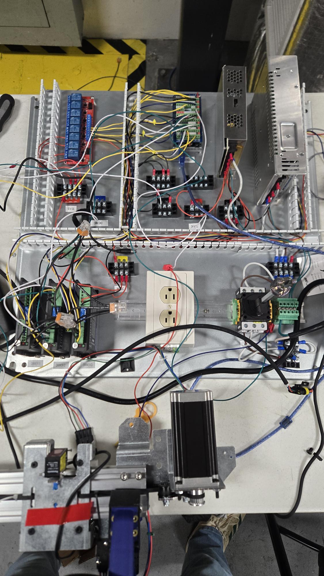
I have two power supplies . For the motors i am using 35 V powersupply and for rest of the stuff like sensors , Led , Relays i am using 24,12,5 volts respectively .
You are using Wago connectors. I find them untrustworthy in so many ways, and trustworthy in a very few ways. Replace them with terminal blocks or soldering.
void setup() {
  // put your setup code here, to run once:
pinMode(23,OUTPUT);
pinMode(24,OUTPUT);
digitalWrite(24,HIGH);

}

void loop() {
  // put your main code here, to run repeatedly:
digitalWrite(23,HIGH);
delayMicroseconds(200);
digitalWrite(23,LOW);
delayMicroseconds(200);
}
I just used this code for testing the stepper motors . Everything seems to be working fine .
Is this issue related to coding? am i giving pulses improperly ? i the code which i have attached i am having issue in troubleshooting Function . inside that there is a if condition which rotates the Left motor Up. Can you check that once if possible .?
The your program is NOT causing the direction to change. There must be an electrical problem. Check that there is not some broken wire or connection problem with the stepper controller board.
Note: substitute one of the other drivers for the one with a problem.