I'm unable to get the motor to turn, it just sort of buzzes around on my desk like an angry bumble bee, making a high pitched between-radio-frequencies/interference sort of a noise.
driver pdf: http://www.kelinginc.net/KL-4030.pdf
motor pdf: http://ge.tt/8X8qBb22/v/0?c
Arduino code:
int pulPin = 5;
int dirPin = 6;

void setup() {
  pinMode(pulPin, OUTPUT);
  pinMode(dirPin, OUTPUT);
}

void loop() {
  digitalWrite(dirPin, HIGH);
  digitalWrite(pulPin, LOW);
  delay(100);
  digitalWrite(pulPin, HIGH);
  delay(100);
}
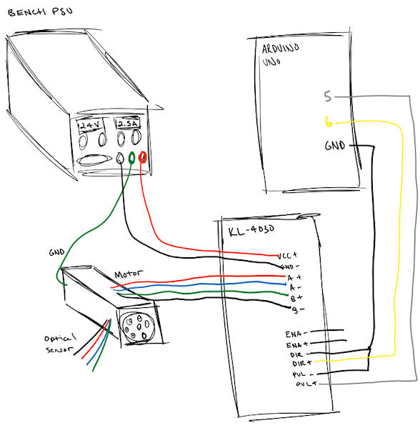
How its wired:
KL-4030 | where it goes
-----------------------------
VCC+    | +24V bench psu
GND     | - bench psu

A+      |  red wire on motor   (see page 10 of motor pdf)
A-      |  blue wire on motor  (see page 10 of motor pdf)
B+      |  green wire on motor (see page 10 of motor pdf)
B-      |  black wire on motor (see page 10 of motor pdf)

EN+     |  unconnected
EN-     |  unconnected
PUL+    |  arduino pin 5
PUL-    |  arduino ground
DIR+    |  arduino pin 6
DIR-    |  arduino ground

M1      |  1
M2      |  1
M3      |  0
M4      |  0
M5      |  0
M6      |  1
M7      |  1
M8      |  0
Really stumped. I don't know if my code is bad, if my wiring is bad, or if one of the components are bad... or even where to begin troubleshooting it. Any suggestions are appreciated.
Thanks!