Hello !
I'm trying to connect my stm32 to a spi screen (controller : ST7735).
In arduino IDE, I picked some sample sketch from ucglib to try my screen, but I get nothing excepted a blank screen.
I connected all the wires from the 8 pins header to the stm32, as follows:
VCC: Power supply +3.3v
GND: Power supply GND
CS: PB10
RESET: PB8
A0: PB9
SDA: PB11
SCK: PB13
LED: Power supply +3.3v
The sample sketch I chosed is "GraphicsTest" and I uncommented this line:
Ucglib_ST7735_18x128x160_SWSPI ucg(/sclk=/ 13, /data=/ 11, /cd=/ 9, /cs=/ 10, /reset=/ 8);
As I understood, pin 13 translates to PB13 etc
But sketch is not working ...
Should I also connect SD_MISO, SD_MOSI, SD_CS & SD_SCK ?
If yes, where should I connect them on the STM32 ?
Thanks a lot for your help !
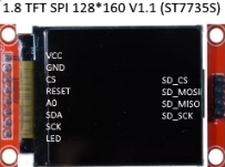
In attachment, the lcd module pinout, and a picture of the module I have.
As I understood, pin 13 translates to PB13 etc
Depends what "etc" means. There is also port A. Such a simple assumption is unwarranted. It would behoove you to verify and/or test each pin individually in some simpler way. It's a good bet that you have the wrong pin(s). Consult a reliable reference too.
You didn't specify which STM32 board you have, there are almost a hundred.
Indeed, I didn't specify the mcu I'm using.
This is the blue pill module.
Br,
Stéphane
aarg:
Depends what "etc" means. There is also port A. Such a simple assumption is unwarranted. It would behoove you to verify and/or test each pin individually in some simpler way. It's a good bet that you have the wrong pin(s). Consult a reliable reference too.
You didn't specify which STM32 board you have, there are almost a hundred.
I did this change (specified the pin in the constructor):
Ucglib_ST7735_18x128x160_HWSPI ucg(/cd=/ PB9, /cs=/ PB10, /reset=/ PB8);
- connected the SD_MOSI, SD_MISO, SD_CS & SD_SCK to PA4,PA5,PA6 & PA7
And the screen is now working !
Happy me 
