I'm have some struggles with the following device:
"1.8" Serial SPI TFT LCD Display Module ST7735B IC + PCB Adapter For Mega2560 R3"
I newer in arduino and buy this item from ebay. The pin configuration of the display does not match with any which i found in the web, can you help me with the identification?
In general, there are some tipical distribution as:
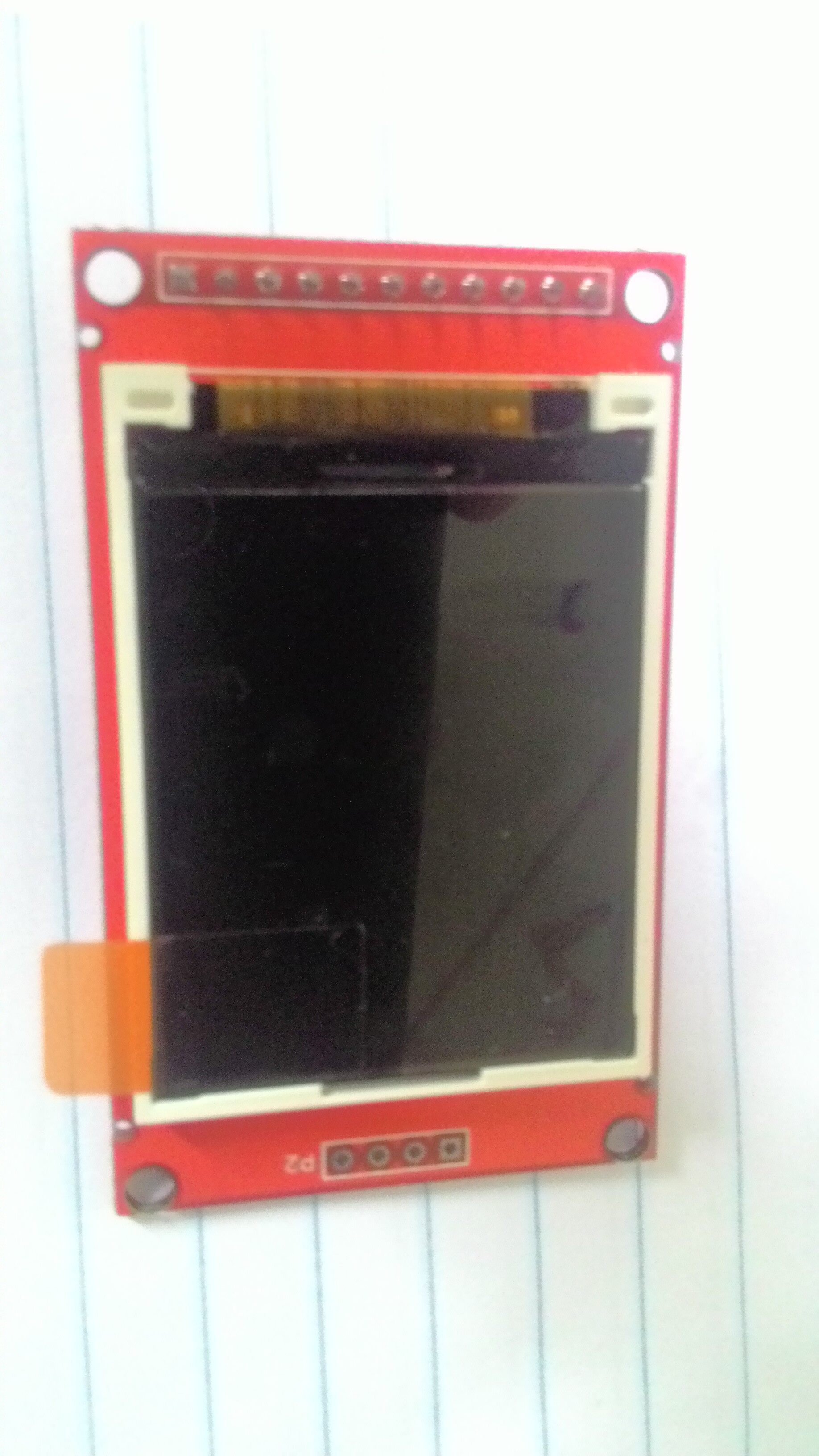
but i get this pin distribution on my display
VCC
GND
GND
NC
NC
NC
CLK
SDA
RS
RST
CS
I had take this pin analysis from Matthias from this forum
Pin description is easy:
11PIN Standard wiring used IO:
VCC--Power supply (5V/3.3V)
GND-- Power supply (GND)
GND-- Power supply (GND)
NC--No connect
NC--No connect
LED-- Pick IO control back light off or PWM brightness control
CLK--SPI clock signal
SDI--Serial data input pin sda
RS--Command (RS=0)/ Parameter (RS=1)
RST--Reset pin
CS-- Chip selection pin
but i have no LED pin, instead i have a NC in place.
I would like the help of some one of you to identify the pin configuration and the advice for some reading material relevant to understand how to manage this display.
I have never seen a ST7735B. Has anyone got a data sheet?
The reason for your "unusual" pinout is so that you can plug it directly into the Power & Analog headers e.g. 5V through to A5. The main attraction is that it will work with 5V logic from a MEGA2560.
If you bit-bash SPI in software, the display will work fine. Unfortunately the HC245 chip is wired as unidirectional. You can only write to the TFT. You can't read SDA pin.
If you want to use hardware SPI, you would need to hand-wire all the pins to the 3x2 SPI header instead of a nice plug-in.
Thank you for the comment, I will try to find the data sheet os try to hand-wire by myself. I'll try to find more bibliography for this because there are a lot of things I need to learn about.
If you know some bibliography to understand a little more about this kind of devices a would be nice.
Your video uses the 5V .. A5 wiring scheme but you have not plugged directly into the Uno.
Of course trailing wires would be needed if you chose any diffeent wiring scheme e.g. to use hardware SPI.
Note that there are two ways to use the display with common Arduino hardware.
VCC..CS to pins 5V .. A0 on the Arduino board.
VCC..CS to pins 2 .. 12 of a HD44780-style LCD header socket on a dev board.
Check your dev board or Arduino LCD Adapter shield carefully before trying method (2)
Personally, I prefer to use standard shields or make a custom Protoshield. Trailing wires are not reliable.
If I have to make a custom adapter, I might just as well use a regular 2.2" SPI display with resistors (or 3.3V GPIO)
These small displays work pretty well with software SPI. I am sure that you will make good projects with it.
Thank you David, I'm revising the wiring and my installation, I'm comparing the library I'm using and understanding, I'm planning some applications for a robot and thermal sensor. I have received from the vendor the information about the display: data sheet, manual, and library. In this moment I'm studying them. You can download from http://pan.baidu.com/s/1bnkEYbd.
If you find a datasheet that specifically says ST7735B I would be very interested.
Mind you, the ST7735R and ST7735S have been on the market for a long time.
Personally, I have never seen an original ST7735.
And regardless of what Ebay and Ali vendors claim, the boards that they sell often contain different controllers. I can understand lingerie shops not knowing too much about electronics. They should be able to match correct photographs with the actual item that they send you.