Strange behavior of the algorithm RTIMULib2 at startup

I use a well-known algorithms RTIMULib or RTIMULib2.
Adapted to the Arduino environment.
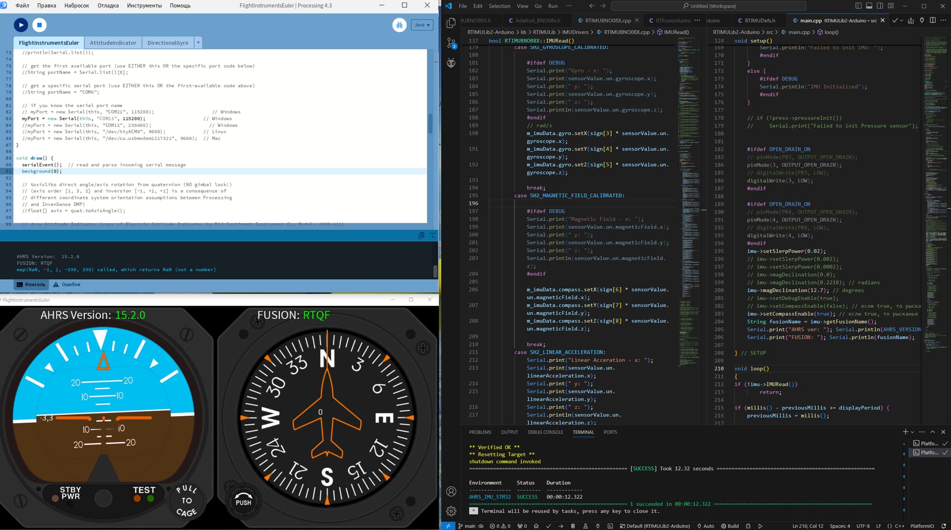
Launched the source code in the vscode + platformio environment on an esp32 microcontroller with a bno055 sensor.

The sensor axes are positioned like this

	//          bno055 sensor.
	//
	//                  | Z axis
	//                  |
	//                  |   / Y axis
	//              ____|__/____
	//            /      | /    /|       X axis
	//           /      |/____//________
	//          /__________* //
	//         |____________|/

I receive data from the sensor using the reading function, which contains the following transmission lines for the accelerometer and gyroscope axes.
I rewrote the library files to work with the sensor via the SPI bus.

RTIMUBNO055.cpp

    //  sort out accel data;

    m_imuData.accel.setX(sign[0] * m_imuData.accel.x());
    m_imuData.accel.setY(sign[1] * m_imuData.accel.y());
    m_imuData.accel.setZ(sign[2] * m_imuData.accel.z());

	//  sort out gyro axes

    m_imuData.gyro.setX(sign[3] * m_imuData.gyro.x());
    m_imuData.gyro.setY(sign[4] * m_imuData.gyro.y());
    m_imuData.gyro.setZ(sign[5] * m_imuData.gyro.z());

    handleGyroBias();
    // calibrateAverageCompass();
    calibrateAccel();

    //  now update the filter
    updateFusion();

Gyro data scaled in rad/sec

I scale the accelerometer data to 9.8 m/s^2

I don't have the magnetometer sensor connected yet, so I'm not using it yet.

I won't post the whole main.c file, those who know the library RTIMULib2 will understand.

#include "RTIMUSettings.h"

#include "IMUDrivers/RTIMU.h"

#include "CalLib.h"

#include "RTFusionRTQF.h"

#define  SERIAL_PORT_SPEED  115200

RTIMU *imu;  

RTIMUSettings settings;

int sign[9] = {1, 1, 1, 1, 1, 1, 1, 1, 1};

void setup()

{

Serial.begin(SERIAL_PORT_SPEED);

imu = RTIMU::createIMU(&settings); 

imu->IMUInit();

imu->setSlerpPower(0.0002);

imu->setCompassEnable(false);

} // SETUP

void loop()
{

if (!imu->IMURead())
        return;

RTIMU_DATA data = imu->getIMUData();

    Serial.print("Orientation: ");
    Serial.print(-data.fusionPose.x() * RTMATH_RAD_TO_DEGREE);
    Serial.print(" ");
    Serial.print(data.fusionPose.y() * RTMATH_RAD_TO_DEGREE);
    Serial.print(" ");
    Serial.println(-data.fusionPose.z() * RTMATH_RAD_TO_DEGREE);

} // LOOP

I added an array sign[9] to change the signs of the axes from the main.c

In general, a question about the strange behavior of the RTQF and KALMANSTATE4 algorithms.

GUI on Processing from GitHub - VoxMi/MPU-9150 with minor modifications.

The RTQF algorithm, when the device is first turned on, for some reason has a rotation around Y axis and begins to align it to the normal position of the sensor.

But it's as if the Z axis has gravity pointing upward.

The KALMANSTATE4 algorithm works perfectly when first turned on, all the axes are correct and there is no additional rotation.

I tried changing/deleting some lines from the source files, it seems like the function

predict()

affects the result of the axis flip.
But I can't understand more.
In general, the algorithms work, but the nature of the orientation flip when running the RTQF algorithm is unclear

Source code RTQF

and

KALMANSTATE4

I have already used the first version of the library RTIMULib in this way with Flight Gear avia simulator.
More info in forum.

If you don't take care that the sensor coordinate systems are right handed, properly and consistently oriented, errors like this are to be expected.

It is worth noting that when an accelerometer is at rest, the Normal force (acceleration that prevents it from falling) points in the up direction.

1 Like

So my coordinate system is right-handed.
The only question is about the algorithm RTQF
For some reason it starts with a flip and rotates the Y axes.
The algorithm KALMANSTATE4 starts normally.
Otherwise, the algorithms work correctly and the entire orientation is correct with minimal errors.
I want to find the start moment in the code and so far I have not been able to do this :roll_eyes:
Maybe there is some peculiarity of the algorithm RTQF initialization, but I don’t know about it?

That is simply a matter of studying the code.

1 Like

For me it's more a question of understanding quaternions and matrices.
Do you happen to know the reason for the rotation around the Y axis at startup?

Quaternions and matrices have nothing to do with "find the start moment in the code".

However, it is absolutely critical to understand the convention adopted by the code for how the body (sensor) axes are oriented in the fixed coordinate system, for the default starting quaternion, for example (1, 0, 0, 0).

A popular choice is that the sensor (X, Y, Z) axes are aligned with NWU (North, West and Up on Earth). The magnetometer is required in order to define North.

How is that relationship defined in RTIMUlib?

1 Like

I understand that.

I have a slightly different axis orientation, Y - north, X - east, Z - up.
Now I use the BNO08x sensor, it seems quite interesting to me in terms of getting data from it.

void RTIMUBNO08X::setReports() {
  Serial.println("Setting desired reports");
// 9.8 G's
  if (!bno08x.enableReport(SH2_ACCELEROMETER)) {
    Serial.println("Could not enable accelerometer");
  }
// rad/s
  if (!bno08x.enableReport(SH2_GYROSCOPE_CALIBRATED)) {
    Serial.println("Could not enable gyroscope");
  }
//uTesla
  if (!bno08x.enableReport(SH2_MAGNETIC_FIELD_CALIBRATED)) {
    Serial.println("Could not enable magnetic field calibrated");
  }
  if (!bno08x.enableReport(SH2_LINEAR_ACCELERATION)) {
    Serial.println("Could not enable linear acceleration");
  }
  if (!bno08x.enableReport(SH2_GRAVITY)) {
    Serial.println("Could not enable gravity vector");
  }
  if (!bno08x.enableReport(SH2_ROTATION_VECTOR)) {
    Serial.println("Could not enable rotation vector");
  }
  if (!bno08x.enableReport(SH2_GEOMAGNETIC_ROTATION_VECTOR)) {
    Serial.println("Could not enable geomagnetic rotation vector");
  }
  if (!bno08x.enableReport(SH2_GAME_ROTATION_VECTOR)) {
    Serial.println("Could not enable game rotation vector");
  }
  if (!bno08x.enableReport(SH2_STEP_COUNTER)) {
    Serial.println("Could not enable step counter");
  }
  if (!bno08x.enableReport(SH2_STABILITY_CLASSIFIER)) {
    Serial.println("Could not enable stability classifier");
  }
  if (!bno08x.enableReport(SH2_RAW_ACCELEROMETER)) {
    Serial.println("Could not enable raw accelerometer");
  }
  if (!bno08x.enableReport(SH2_RAW_GYROSCOPE)) {
    Serial.println("Could not enable raw gyroscope");
  }
  if (!bno08x.enableReport(SH2_RAW_MAGNETOMETER)) {
    Serial.println("Could not enable raw magnetometer");
  }
  if (!bno08x.enableReport(SH2_SHAKE_DETECTOR)) {
    Serial.println("Could not enable shake detector");
  }
  if (!bno08x.enableReport(SH2_PERSONAL_ACTIVITY_CLASSIFIER)) {
    Serial.println("Could not enable personal activity classifier");
  }
}

For now I use only three parameters:

SH2_ACCELEROMETER
SH2_GYROSCOPE_CALIBRATED
SH2_MAGNETIC_FIELD_CALIBRATED

But in the future I want to try using:

SH2_LINEAR_ACCELERATION
SH2_GRAVITY
SH2_ROTATION_VECTOR
SH2_GEOMAGNETIC_ROTATION_VECTOR

Right now the RTIMUlib2 library already has gravity calculation and subtraction, so I want to compare the results.
https://github.com/HongshiTan/RTIMULib2/blob/df69ac6dfc248970dbf01e41c03c2071b73eee7e/RTIMULib/RTFusion.cpp#L133
I oriented the board on the device like this.
In the RTIMUlib2 code, I specified the orientation of the axes like this
m_axisRotation = RTIMU_XNORTH_YEAST;
And here's the strange thing, from the BNO08x datasheet, the axes should be located like this

BNO08X axis orientation

but in fact, either in the RTIMUlib2 code the orientation does not correspond to the name
RTIMU_XNORTH_YEAST
Either I don't understand anything, but the code works and determines the correct orientation, nevertheless.

I don't quite understand the array in the code
https://github.com/HongshiTan/RTIMULib2/blob/df69ac6dfc248970dbf01e41c03c2071b73eee7e/RTIMULib/IMUDrivers/RTIMU.cpp#L60
Why is the axis Z of the magnetometer equal 1, i.e. it is directed upwards?
I probably need a little more time to figure out the orientation of the axes implemented in the RTIMULib2 algorithm.

You have been working on these issues for a long time and specifically RTIMUlib, and I read somewhere on the forum that you do not use RTIMUlib2, I wonder why?
I also used RTIMUlib for some time, but there was no Kalman filter, which appeared only in RTIMUlib2 and I was interested in trying it out.
I may confuse definitions and call algorithms "filters", but I hope you understand me.
But the paradox is that without a magnetometer, the RTFusionKalman4 filter works better than with a magnetometer, and the RTFusionRTQF filter, on the contrary, without a magnetometer, begins to flip the axis at startup, as shown above in my video, but with a magnetometer it works much better and more accurately than Kalman4.
I have an opinion, it may not be objective, but Kalman4 in the RTIMUlib2 library is a trick, and in fact it is a lightweight version of Kalman filtering.
I would like to hear your opinion on this matter and maybe you know where I can find out more information about the functionality of these two algorithms:

https://github.com/HongshiTan/RTIMULib2/blob/df69ac6dfc248970dbf01e41c03c2071b73eee7e/RTIMULib/RTFusionRTQF.cpp
https://github.com/HongshiTan/RTIMULib2/blob/df69ac6dfc248970dbf01e41c03c2071b73eee7e/RTIMULib/RTFusionKalman4.cpp

In general, the algorithm code works and I am satisfied with it, but I would like to understand the calibration of accelerometers, gyroscopes and magnetometers.
As far as I understand, the calibration functions are launched from the function

IMURead()

for each sensor this function is implemented differently, for some the data is received in a buffer, for others in a FIFO, but this does not change the essence - raw data is always received, which must be filtered, offsets removed and scaled.
In my code for the BNO08x sensor, the calibration functions are as follows:

handleGyroBias();
RTIMULib2/RTIMULib/IMUDrivers/RTIMU.cpp at df69ac6dfc248970dbf01e41c03c2071b73eee7e · HongshiTan/RTIMULib2 · GitHub

calibrateAverageCompass();
RTIMULib2/RTIMULib/IMUDrivers/RTIMU.cpp at df69ac6dfc248970dbf01e41c03c2071b73eee7e · HongshiTan/RTIMULib2 · GitHub

calibrateAccel();
RTIMULib2/RTIMULib/IMUDrivers/RTIMU.cpp at df69ac6dfc248970dbf01e41c03c2071b73eee7e · HongshiTan/RTIMULib2 · GitHub

I removed all dependencies in the code that allowed loading the RTIMULib.ini file, and as I understand it, it contained settings for all offsets for calibrating accelerometers, gyroscopes and magnetometers?
I would like to find a solution that allows for in-device calibration, but I only find solutions with preliminary measurements, entering everything into the magneto program or similar, and then manually entering calibrations into the program code.
Could you help and suggest some answers to my questions?
I will be glad to discuss with you.
P.S. If you use vscode + platformio and you have sensors BNO055 or BNO08x I can share with you the modified RTIMULib2 code so that we can do the same steps.

This topic was automatically closed 180 days after the last reply. New replies are no longer allowed.