Even if you use Logic Level versions, you still need to know the gate voltage at which a certain current can be turned on. I think that you need a PWM with RC-filter for the gate.
Measuring a few millivolts (drain-source) will not be easy. Are you adding a OpAmp ?
Making good contact with a temperature sensor is also not easy.
Your design should use kelvin contacts wherever needed. How are you going to determine the die temperature as the threshold changes with temperature. Do you have the analog skill set this will require? When we measured the Gate threshold voltage of a MOSFET, we shorted the Gate to Drain then set up our ID at 250μA. At this point we could monitor the voltage difference between Gate-Source. Please note the VGS(TH) has a negative temperature coefficient. After you build this how are you going to assure calibration?
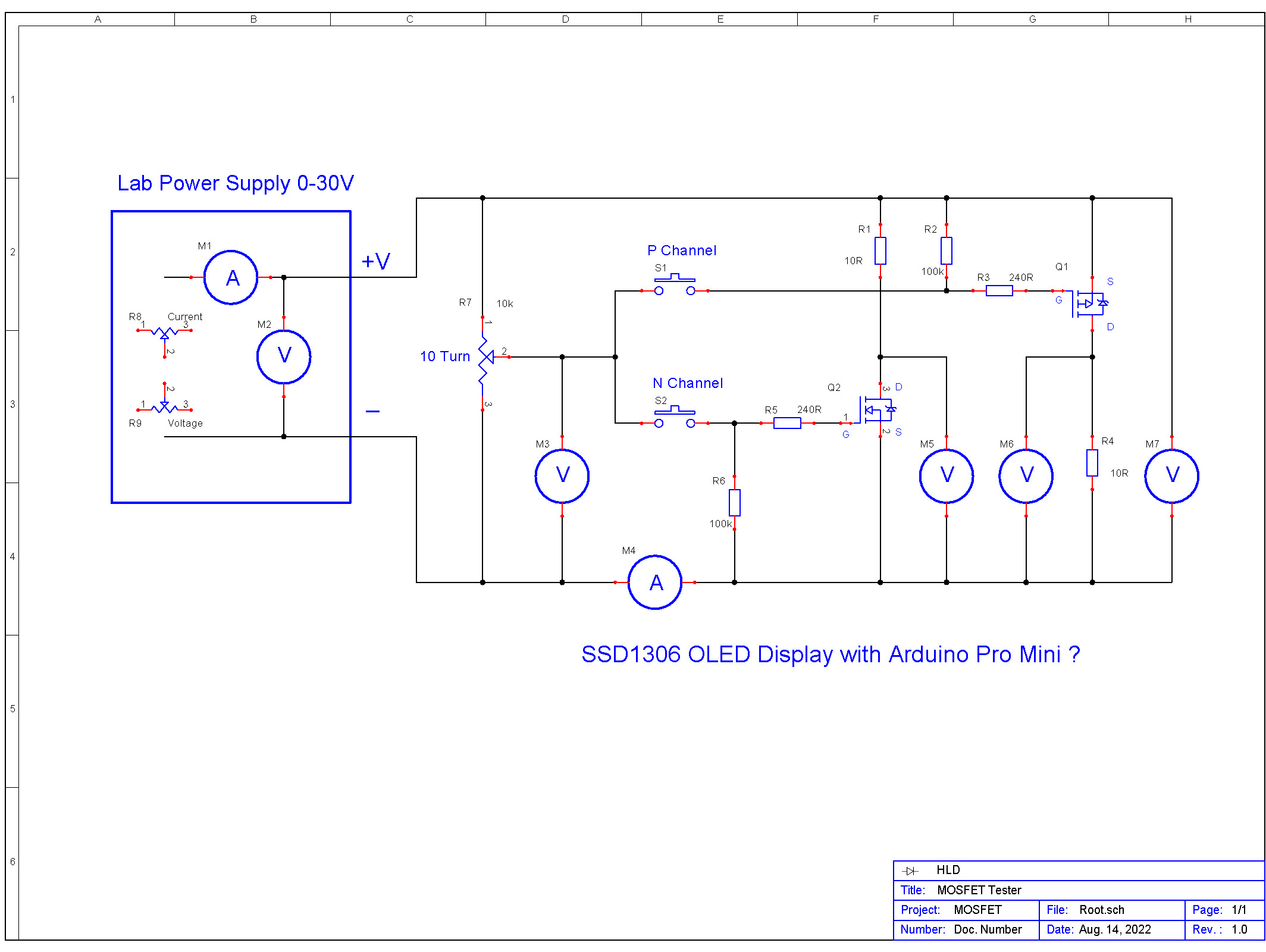
Will add an Arduino Pro Mini and a SSD1306 OLED display.
The display will show Vgs from the 10 turn pot, Vds to see if the MOSFET is fully ON and Rds(on) as calculated from the current flowing divided by Vds.
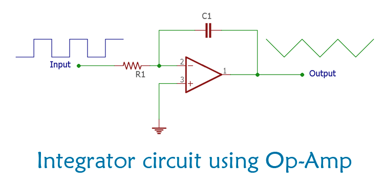
I like @Koepel 's idea using PWM instead of the 10-turn pot. Using Timer1, could get 12-bit resolution at 3.9 kHz PWM frequency, therefore near 1mV resolution. Very little ripple if you use 10K/1μF, fast enough response (cutoff freq at about 16Hz). Test here.
Another advantage is being able to automatically program a series of voltage levels and generate a response curve.
No Larry, I was going to get one but its very similar to other rrss op amps I've tested.
I'll point this out as a general note - "rail to rail" op amps can not maintain rail to rail outputs if supplying current.
So should you remove the R5 & D1? Of course if D1 is not plugged in for testing it wont change the "gate" voltage; and if youre testing the LED the IV curve will still be valid.