thanks ![]()
are you saying that the driver is not good to use? can you recommend other motor driver for prototype projects
No it is a great part, I have recommended it many times and use a lot of them. The fault is in your circuit not the module. PCB traces melt and ICs fail because of overvoltage, current, etc. In your case I have no clue as I did not see the fault occur or the FA (Failure Analysis). You are using a module, that also has other ICs on it which also must not be overdriven. Can you post your Design FEMA (Failure Effect Mode Analysis) if you did one?
At this point I believe it is a hardware application problem. Post a complete and annotated schematic and list the part numbers on the BTS7960 module. I have seen several versions of this module with similar and different logic family ICs. They have different Power and input values.
........HC...................HCT
min. typ. max. min. typ. max.
2.0 5.0 6.0 4.5 5.0 5.5 V
Good Luck.
1 Like
I'm sorry, but we don't have it and we don't know how to make it. If ever, how can we do that?
Can I ask what you mean by an annotated schematic? What should I include from the latest schematic diagram I uploaded above?
Might also say this here, the technician at the store where we bought the BTS7960 said that the sudden surge probably burned the ICs of the motor drivers based on the code we used. They suggest adding some lines of code where soft start and stop/deceleration will occur. For example, if the motor is moving forward and we suddenly want to take a reverse, they suggest that deceleration should happen first before proceeding to reverse. Is this correct?
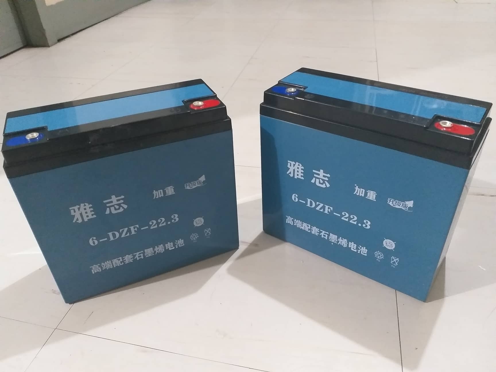
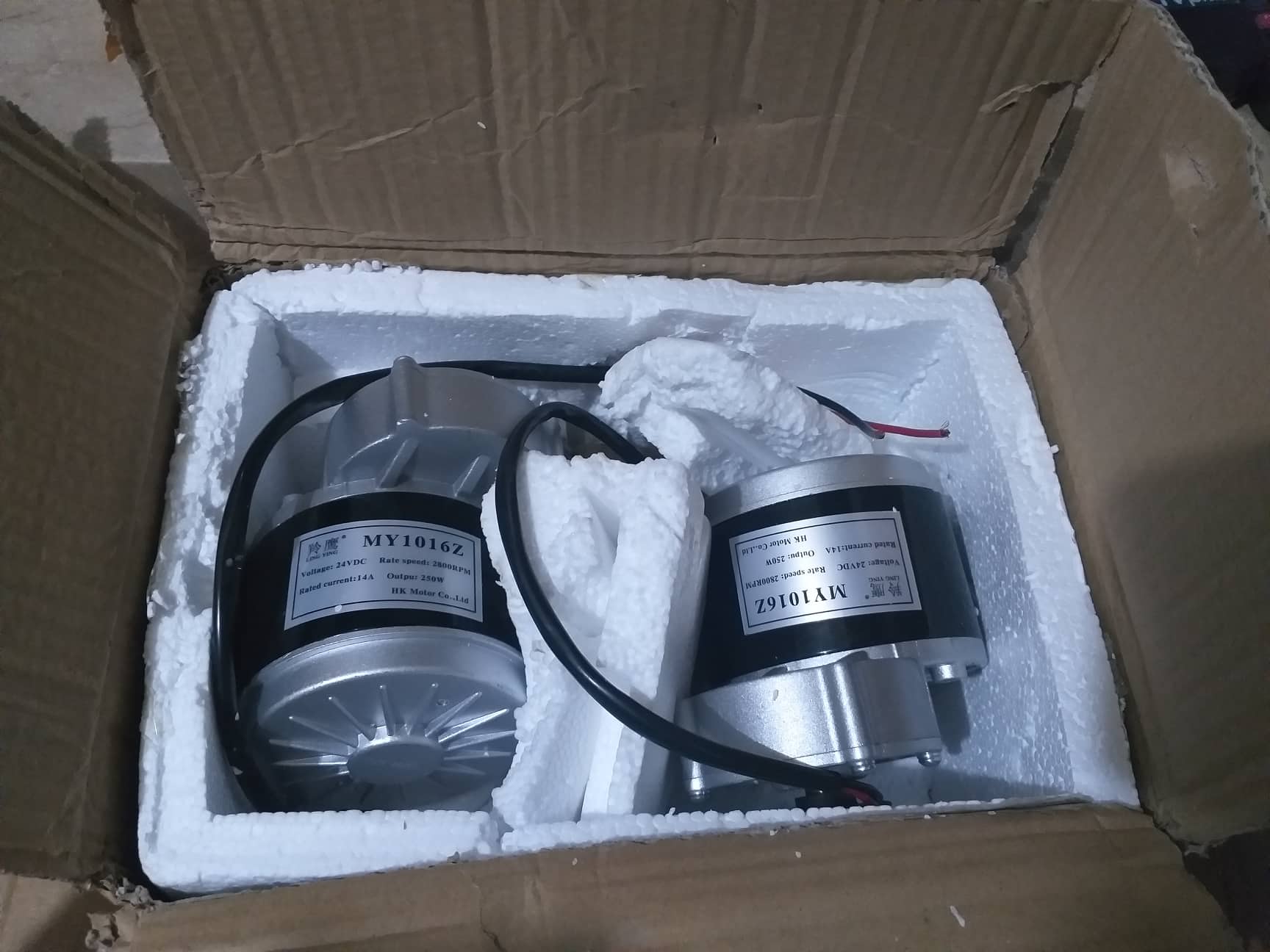
And for the hardware, currently we are using this kind of DC Motor and Power Supply:
FMEA is a critical part of design, mandated by some OEMs such as Automotive. Here is a link that may help: 10 Steps to do a Process Failure Mode and Effects Analysis
There is the ability to annotate a schematic in most CAD programs such as KiCad and Alturm. The Annotate Schematics command systematically assigns designators to all or selected parts in selected sheets of a project and ensures that designators are unique and ordered based on their position You can search for "annotated schematic" there are a lot of links many dependent on the tools you are using. Your schematic is missing a lot of information.
Sudden surge I cannot agree with or disagree with without a lot more information. The tech is correct, going from full in one direction to full in the opposite direction pushes lots of amps through the motor circuit and its associated drivers. There is more then enough current to blow some small logic traces especially if there is a bad connection. Without knowing the failure mode of the Bridge the best will be a guess. Be sure you have solid grounds and that the logic voltage is in proper range.
Hopefully this will help.
I'm sorry, but I don't think I can provide those things as I have only a little knowledge and our deadline is near ![]()
Can I ask again, what do you mean by annotated? Or what do you want to see? Do you mean that I should fix my current schematic diagram where PWM pins were not connected into PWM of Arduino? Or does it mean something else?
What do you mean by not being connected to the logic ground?
Double BTS7960 43A H Bridge High Power Stepper Motor Driver Module | Lazada PH
This is the link where we bought our BTS7960 module.
Aside from that, can you give some comment regarding the hardware connections? Based on the other forums I've read with similar topics, they used fuses between motors and power supply in the ground connection if I am not mistaken. Should we also use them?
Also, regarding the code, could you also check it? Regarding the soft start and stop between directions of the motor, do you have any idea on how to execute that?
Apologize and thank you for your response! Our group highly appreciates your help in creating our prototype ![]()
Did you blow a fuse in the ground line? There should not be one there it should be in the + supply. The ground of the battery needs to be connected to the ground of the logic unless the control signals etc are galvanically isolated.
Here is an example of an annotated schematic: https://image.dfrobot.com/image/data/DRI0018/DC%20Motor%20Driver%202x15A_lite%20SCH.pdf Try this link it should help a lot: How to Read a Schematic - SparkFun Learn
Sorry on the code that is not my expertise.
You need to get the person that has the knowledge about the design involved. It is probably the person that designed it. At this point we are a long way from finding your solution, we do not even know what the problem is or why it happened, just the result.
I don't see how such a fragmented drawing can help in finding design bugs. It only can help a person that compares a layout with the design. As we don't have the circuit at hand such a representation is quite useless.
No. We don't use fuse at all.
Can I ask what is the ground of logic?
At this point I would suggest you get somebody local to you with some electronics experience to help you with your design. I do not have the skill set or documentation to help you any further as you do not understand what I am trying to say. Doing a few tutorials on basic electronics would help you understand what is happening. You can also check out from your local library or purchase a book called electronics for dummies, it has a lot of good information that will help you.
This topic was automatically closed 180 days after the last reply. New replies are no longer allowed.